Download
1 / 35
350 likes | 512 Views
Data Compression Module ( DCM ). CDR Status Report. Tong-Long Fu Laboratory of RF-MW Photonics, Department of Physics National Cheng Kung University, Tainan, Taiwan. Outline. Status Review Image analysis and compression ratio achieved Hardware Review Function Testing Conclusions.

E N D
Data Compression Module( DCM ) CDR Status Report Tong-Long Fu Laboratory of RF-MW Photonics, Department of Physics National Cheng Kung University, Tainan, Taiwan
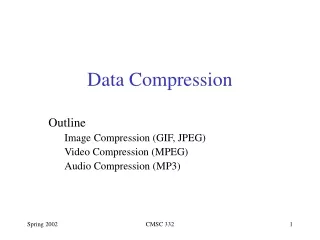
Outline • Status Review • Image analysis and compression ratio achieved • Hardware Review • Function Testing • Conclusions
Status Review Works have been done: Hardware • All measurement instruments and tools ready • 2. Testing environment ready • Interface with MMCB/DPU discussed/reviewed. • Compete ETU version A. Software • Carry out image testing and analysis • Settle coding scheme. • Check coding size and memory map. • complete FPGA Design. future works: Hardware Testing and Integration testing. Software Code Optimization
Image Analysis • Image analysis • Coding work flow • Windowing method • Compression code and compression ratio achieved • Programming • Code size, …
Image Analysis (1)for Image Compression 1.Typical Images are Sprite Image Aurora Image Airglow Image 2.Other type of data (from SOH,SP,AP) - minor issue Most critical Typical 512x128 image will be directly compressed
x x y y x y Image Analysis (2)for sprite Star and lightning will also be picked up . Threshold and window size are critical.
x y x y x y Image Analysis (3)for Sprite Star and lightning will also be picked up . Threshold and window size are critical.
x x y y x y Image Analysis (4)for Sprite The background of image is too noisy. Coding scheme and automatic window selection are difficult.
x y x y Image Analysis (4)for Sprite This image has two sprites simultaneously x y Imaging should be compared every two successive images.
Store 2 images IMAGE DATA Coding work flow Store Image Windowing image Sprite image yes No (windowing code) Coding Image (range code) IMAGE DATA Packet
Store 2 images in the DCM Do low pass filtering Windowing Method Image input Compare two images , search different parts (high value ) Store windowing parameters Set values outsize the windows to be zero Coding image
Windowing Parameters -Windowing an optimized windowing need to optimize -Window Size -we need to determine 16x16,32x32,64x64) -Image ordering -we need to record the order of image stored - Threshold for windowing CDI Command or MMCB * We need to include the selection of windowing parameter in CDI and/or MMCB
Compression Code (1)range code BMP file Use range coding 66K 19K Compression ratio: 3.5 66K 7K Compression ratio: 9.4 • range coding is only an 1D data compression coding. • It is not a good compression algorithm for image coding.
Compression Code (2)Predictor code and range code Use PGM file Predictor coding Rangecode : compression ratio 4 Huffman code + Predictor code : compression ratio 4.85 (Lossless JPEG standard method) No good data for coding and some data like noise. Call “weeds in a football field”. A problem for lossless compression coding
Range code Company code A Compression ratio 6.7:1 (order 4) 5.0:1 Compression ratio 2.1:1 (order 3) 2.0:1 Compression ratio 4.5:1 (order 3) 3.2:1 Compression ratio 2.0:1 (order 4) 1.85:1 B C D Compression Code (3)comparison with a commercial Company C D A B
Company Phone: (813) 875-7575 x303 FAX: (813) 875-7705 - Pegasus - BETTER DIGITAL IMAGING http://medical.jpg.com
Compression Code (4)general image PGM file We need to get the standard sample image to do coding optimization . Typical image needs to have the same parameters of image. e.g. Histogram , pixel/bits. Range code : compression ratio 3 Huffman code + Predictor code : compression ratio 6.9 (Lossless JPEG standard method)
Programming Consideration(1)Memory Size Memory Size: 1. BIOS (EEPROM) 32K x 48 (Control code and some compression code) 2. Program Memory (SRAM) 128K x 48 -- Total 768 bytes 3. Data Memory (SRAM) 128K x 40
Programming Consideration(1)Image Memory Size 512 x 128 Pixel : (16bits / Pixel ) 128k byte (1) If we use C code to program DSP, we can only use the limited integer type. Type of Integer : ( 32bits / Pixel ) So store two images = total Data memory of DCM (2) Suggested solution : 1. Change to write the codes in assembler.
Programming Consideration(3)code size -Range code only 24K bytes (without global data setup)
Compression Coding Summary • All simulation of image is 8 bits image. (Need to consider about 16 bits) • Range Code + Predictor Code + Windowing Code is the finial scheme of coding. • All Program size < 200 Kbytes. • PLB section in MMCB is to store the upload program. If we want to let DCM to have new upload program code, then DCM will load program from PLB in the MMCB. • If we need do movie compression coding of Aurora Image,we maybe need more memory for coding.
Hardware Review • Interface summary • List of key parts • Modification since IFR • PCB • Memory size
Hardware Review(1)Interface summary Interface - Between DPU and DCM 1.DCM_BSY 2.DCM_ATN 3.CDI-CCLK 4.CDI-DAT 5.CDI-STB - Between MM and DCM 1. Address Bus (26bits) 2. Data Bus (32bits) 3. Read/Write enable 4. DMACK
Hardware (3)Modification since IFR Due to the limit of ADI DSP chip, we have to make the following modifications -- Program Memory: (now 128K x 48) -- Data Memory: (now 128K x 40) -- EEPROM Memory: (now 128K x 48)
Hardware (4)PCB configuration -ADSP21020 DIP and SMD -FPGA A1280A FPGA A54SX six ERPOM in this
Hardware (6)FPGA Note Target Part: 54sx16p-s -Combinational Cells: 181 of 924 (20%) -Sequential Cells: 167 of 528 (32%) -Total Cells: 348 of 1452 (24%) -Clock Buffers: 2 -IO Cells: 44
Function Testing • Testing tools • Testing ports
Function Testing (1)Testing Tools -ICE: Coding debugging -Silicon II: FPGA Testing DCM - Board Testing: CDI Testing Interrupt Testing
Function Testing (2)Tool Description (1) Using Testing Port : FPGA ALTERA EPF10 1. Program function form LPT1. 2. Support 10MHz and 2 MHz clock . 3. Connect Testing Port . (2) Using ICE Testing : 1.Testing Program Code. 2. Testing Memory Save and Load. (3)Using FPGA Silicon Testing Port: Testing FPGA action function.
Testing Function (3)Testing Ports Signal Bus Bus
Conclusions -Schedule July: 1.Hardware Testing and Software Testing. 2. Check integration testing schedule. (build up a testing environment in UCB during CDR.) August: 1.Optimize coding 2. Finalize DCM ETU board testing. September: 1. Finalize all testing