Download
1 / 29
290 likes | 302 Views
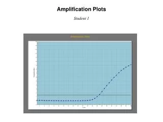
Amplification and Feedback. ESS205 Spring 2004. How stable should frequency be as voltage is changed?. LM555 datasheet – 0.3% per volt, typical. Disk ceramic. Monolithic ceramic. Mylar film. Frequency stability vs. voltage. Actual components have many non-ideal characteristics

E N D
Amplification and Feedback ESS205 Spring 2004
How stable should frequency be as voltage is changed? LM555 datasheet – 0.3% per volt, typical
Disk ceramic Monolithic ceramic Mylar film Frequency stability vs. voltage • Actual components have many non-ideal characteristics • Temperature coefficients, voltage coefficients, memory effects, drift… • Specifications matter!
555 lab followup • Stability of oscillation frequency as power supply voltage is varied • Erratic measurement of frequency with multimeters
Frequency Meters • Need AC voltage > 250 mV RMS to determine frequency • Some show sensitivity to voltage “spikes” • Putting resistor in series with meter improves performance – low pass filter effect Good reading Bad reading
Amplifiers • Make a signal (voltage or current) bigger • Voltage amplifier: Voltage out = Voltage in x G (gain) • Small signals: Sensor outputs, radio reception, microelectronics • Big signals: Provide mechanical energy (motors, speakers), radio transmission, heating
The ideal amplifier G Vin Vout = G x Vin
Amplification devices • Mechanism in which a small signal controls a large signal • Water analogy: turning the faucet (small signal) controls large flow of water (big signal)
Anode electrons Heater Cathode Vacuum tubes • Electrons “boil” off of heated cathode • Voltage on grid(s) control current reaching anode
Transistor • Invented 1947 • Made of semiconductors – silicon, germanium, gallium arsenide • Layered structure – creates junctions The first transistor – Bell Labs, 1947
Transistors • Voltage between base and emitter controls current between collector and emitter • Types: bipolar (NPN, PNP), JFET, MOSFET ~ 1 mm
Approximate transistor behavior – the Ebers-Moll equations • Explicit temperature dependence • Parameters (aF, aR, IES, ICS) dependent upon manufacturing details, temperature, etc.
Simple device – complicated behavior • The physical laws which describe electronic behavior are not simple • Want to make electronic components “act” simple to make them easier to apply • Need to build a complicated device to get simple behavior!
How to make electronics “act” simple? • Emphasize use of components which have close to ideal behavior • Resistors, capacitors • Use circuits which are inherently self-compensating for nonideal behavior • Ex: voltage divider
Modern operational amplifiers ~ 1 mm LT1006 LMH6642
G Vin Vout = G x Vin What’s a good “building block” for amplification? • One option: Fixed gains (10, 100, etc) • Instrumentation amplifier • Another option: Make G…really big, then “throw away” gain you don’t need
Operational amplifiers • G very large (AD820: G ~= 1 million (DC, low load)) • Inputs draw little current (AD820: ~10 pA) V+ Vout=G x (V+-V-) V-
Feedback amplifier • Feedback: output “feeds back” to input • Op amps are always used with feedback • How does this work? G Noninverting Feedback Amplifier
Rationale for use of feedback amplifiers • Amplifier performance is dictated largely by the behavior of simple passive components (e.g. resistors, capacitors) • Pioneers: H. S. Black, H. Nyquist, H. W. Bode, Ball Laboratories, 1920’s “Black’s patent application was delayed for more than nine years in part because the concept was so contrary to established beliefs that the Patent Office initially did not believe it would work. They treated the application in the same manner as one for a perpetual motion machine.” -- W. M. Siebert, Signals and Systems
Basic op amp configurations • Noninverting • Inverting
Quick analysis of op amp circuits • Because G is so large, the difference between V+ and V- must be very small • To a good approximation V+=V- • Ex: V- is the output of a voltage divider: V- = Vout * R2/(R1+R2). V+ = V-, so Vout = V+ (R1+R2)/R2.
Other op amp configurations • Endless variety of circuits for performing different functions: filtering (high pass, low pass, band pass, band reject), integration, differentiation, calculating logarithms, square roots, etc. • Use different feedback components and interconnections Ex: Sallen-key lowpass filter
Buffer amplifier • Gain of 1 – why use it at all?
Output impedance • Ideal voltage source: Voltage independent of load • Real voltage source: Acts like an ideal voltage source in series with a resistor • Small resistance = “low output impedance” Ideal Real
Ex: Voltage divider No buffer amplifier: Vout depends on RL With buffer amplifier: Vout Independent of RL
Buffer amplifier – gain of 1 • Buffer amplifier decreases the output impedance of a signal • Makes it easier to transmit signals between parts of a circuit – enables modular construction
Op amp packaging • Generally 1, 2, or 4 to a package • Standard pinouts Single Dual Quad
Other op amp parameters • Speed (slew rate, bandwidth) – what type of signal can be amplified • DC, audio, video • Precision (input offset voltage) – how closely does the op amp equalize its inputs • Power (supply current, output current) – how much power does the amplifier require, and how much power can it deliver to a load
Input and output range • Op amp can only amplify signals within a range set by its power supply – can limit applications • “Single supply” op amps have input and output voltage range extending to the negative supply Dual supply Single supply