Download
1 / 1
10 likes | 68 Views
UPPER EXTREMITY BIOMECHANICAL MODEL for EVALUATION of PEDIATRIC JOINT DEMANDS DURING WHEELCHAIR MOBILITY. Alyssa Paul 1 -2 , Brooke A. Slavens 2 -4 , Adam Graf 5 , Joseph Krzak 5 , Lawrence Vogel 5 and Gerald F. Harris 1-2,5.

E N D
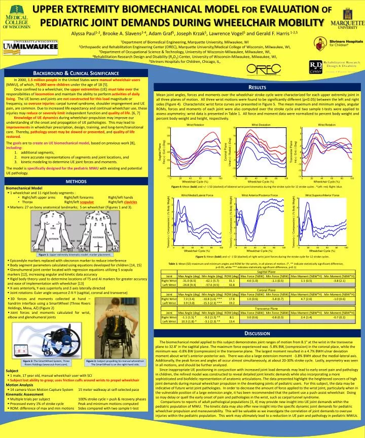
UPPER EXTREMITY BIOMECHANICAL MODEL for EVALUATION of PEDIATRIC JOINT DEMANDS DURING WHEELCHAIR MOBILITY Alyssa Paul1-2, Brooke A. Slavens2-4, Adam Graf5, Joseph Krzak5, Lawrence Vogel5 and Gerald F. Harris1-2,5 1Department of Biomedical Engineering,Marquette University, Milwaukee, WI 2Orthopaedic and Rehabilitation Engineering Center (OREC), Marquette University/Medical College of Wisconsin, Milwaukee, WI, 3Department of Occupational Science & Technology, University of Wisconsin-Milwaukee, Milwaukee, WI, 4Rehabilitation Research Design and Disability (R2D2) Center, University of Wisconsin-Milwaukee, Milwaukee, WI, 5Shriners Hospitals for Children, Chicago, IL, Background & Clinical Significance • In 2000, 1.5 million peoplein the United States were manual wheelchair users (MWU), of which, 79,000 were children under the age of 18 [5]. • Once confined to a wheelchair, the upper extremities (UE) must take over the responsibilities of locomotionand maintain the ability to perform activities of daily living. The UE bones and joints are not constructed for this load magnitude or frequency, so overuse injuries: carpal tunnel syndrome, shoulder impingement and UE pain, are common. Due to increased life expectancy and continual wheelchair use, these injuries may reduceor severely limit independent function and quality of life. [6, 7] • Knowledge of UE dynamics during wheelchair propulsion may improve our understanding of the onset and propagation of UE pathologies. This may lead to improvements in wheelchair prescription, design, training, and long-term/transitional care. Thereby, pathology onset may be slowed or prevented, and quality of life restored. • Thegoals are to create an UE biomechanical model, based on previous work [8],including: • additional segments, • more accurate representations of segments and joint locations, and • kinetic modeling to determine UE joint forces and moments. • The model is specifically designed for the pediatric MWU with existing and potential UE pathology. Results Mean joint angles, forces and moments over the wheelchair stroke cycle were characterized for each upper extremity joint in all three planes of motion. All three wrist motions were found to be significantly different (p<0.05) between the left and right sides (Figure 4). Characteristic wrist force curves are presented in Figure 5. The mean maximum and minimum angles, angular ROMs, forces and moments of each joint were also computed over the stroke cycle and two sample t-tests were applied to assess asymmetry; wrist data is presented in Table 1. All force and moment data were normalized to percent body weight and percent body weight and height, respectively. methods Figure 4: Mean (bold) and +/- 1 SD (dashed) of bilateral wrist joint kinematics during the stroke cycle for 12 stroke cycles . *Left: red; Right: blue. • Biomechanical Model • 1 wheelchair and 11 rigid body segments : • Right/left upper arms Right/left forearms Right/left hands • Thorax Right/left scapulae Right/left clavicles • Markers: 27 on bony anatomical landmarks; 5 on wheelchair (Figures 1 and 3). • Epicondyle markers replaced with olecranon marker to reduce interference • Body segment parameters calculated using equations developed for children [14, 15] • Glenohumeral joint center located with regression equations utilizing5 scapula • markers [12], increasing angular and kinetic data accuracy • Rigid body theory used to determine locations of TS and AI markers for greater accuracy and ease of implementation with wheelchair [13] • X-axis anteriorly, Y-axis superiorly and Z-axis laterally directed • Joint rotations: Euler angle sequence Z-X-Y (sagittal, coronal and transverse) • Subject • 1 male, 17 year old, manual wheelchair user with SCI • Subject lost ability to grasp; uses friction cuffs around wrists to propel wheelchair • Motion Analysis • 14 camera Vicon Motion Capture System 15 meter walkway at self-selected pace • Kinematic Assessment • Multiple trials per subject 100% stroke cycle = push & recovery phases • Processed every 1% of stroke cycle Peak and minimum motions computed • ROM: difference of max and min motions Sides compared with two sample t-test Figure 1: Upper extremity kinematic model: marker placement. Figure 5: Mean (bold) and +/- 1 SD (dashed) of right wrist joint forces during the stroke cycle for 12 stroke cycles . • Table 1: Mean (SD) maximum and minimum angles and ROM for the wrists, in all planes of motion. (*, ** indicate statistically significant difference, p<0.05, while *** indicates statistically significant difference, p<0.1) • 3D forces and moments collected at hand – handrim interface usinga SmartWheel (Three Rivers Holdings, Mesa, AZ) (Figure 2) • Joint forces and moments calculated for wrist, elbow and glenohumeral joints Discussion The biomechanical model applied to this subject demonstrates joint ranges of motion from 8.1° at the wrist in the transverse plane to 32.8° in the sagittal plane. The maximum force experienced was -5.8% BW, (compression) in the coronal place, while the minimum was -0.8% BW (compression) in the transverse plane. The largest moment resulted in a 4.7% BWH ulnar deviation moment about wrist’s anterior-posterior axis. There was also a large extension moment -3.8% BWH about the medial-lateral axis. Additionally, the peak forces and angles all occur almost simultaneously, at about 20-30% stroke cycle. Lastly, asymmetry was seen in all motions, and should be further analyzed. Since inappropriate UE positioning in conjunction with increased joint load demands may lead to early onset pain and pathology in children, the refined model was constructed to reveal detailed joint kinetic demands while also incorporating a more sophisticated and biofidelic representation of anatomic articulations. The data presented highlight the heightened concern of high joint demands during manual wheelchair propulsion in the developing joints of pediatric users. For this subject, the data may be indicative of future wrist joint pathologies. In order to decrease the amount of force applied to the wrist joint, particularly when in the vulnerable position of a large extension angle, it has been recommended that the patient use a push-assist wheelchair. Doing so may delay or quell the early onset of pain and pathologies in the wrist, such as carpal tunnel syndrome. Comparisons to reports of adult pathological populations [3, 4] may provide new insight into UE joint demands within the pediatric population of MWU. The kinetic data may also offer new insight into the specific dynamic joint demands for pediatric wheelchair propulsion and maneuverability. This will be valuable as we investigate the correlation of joint demands to overuse injuries within the pediatric population. This work may ultimately lead to a reduction in UE pain and pathology in pediatric MWUs. Figure 2: The SmartWheel System, Three Rivers Holdings (www.out-front.com). Figure 3: Subject propelling his manual wheelchair. The SmartWheel is on the right-hand side.