Download
1 / 38
380 likes | 383 Views
This mitigation standard outlines the required construction methods to resist radon entry and prepare new residential buildings for post-construction radon mitigation, if necessary. Techniques include subfloor preparation, aggregate placement, use of geotextile matting, soil gas retarder installation, closing potential radon entry routes, and sealing duct systems.

E N D
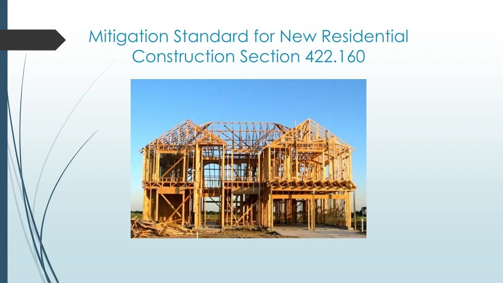
Mitigation Standard for New Residential Construction Section 422.160
Mitigation Standard for New Residential Construction • These are the required construction methods intended to resist radon entry and prepare the building for post-construction radon mitigation, if necessary. • These techniques are required in all areas of Illinois.
Subfloor Preparation The rule states • A layer of gas-permeable material shall be placed under all concrete slabs and other floor systems that directly contact the ground and are within the walls of the living spaces of the buildings, to facilitate future installation of a sub-slab depressurization system, if needed.
AggregateWhat you should have • A uniform layer of clean aggregate, a minimum of 4 inches thick. The aggregate shall consist of material that will pass through a 2 inch sieve and be retained by a ¼ inch sieve
AggregateIf sand or material with fines • A uniform layer of sand (native or fill), a minimum of 4 inches thick, overlain by a layer or strips of geo-textile drainage matting designed to allow the lateral flow of soil gases. Sand Geo-textile mat With fines
Geotextile Matting • The geotextile matting shall have a cross-sectional area of not less than 12 square inches • Shall be placed, at a minimum, along the entire inside perimeter of the foundation at a distance of 12 to 18 inches distance from the foundation wall to the edge of the drainage matting. • Deviation from the 12 to 18 inches distance to the foundation wall shall be allowed to avoid obstacles such as plumbing and other utilities
Soil Gas Retarder • A minimum 6-mil or 3-mil cross-laminate polyethylene or equivalent flexible sheeting material covers over the top of the gas permeable layer prior to casting the slab or placing the floor assembly to serve as a soil gas retarder by bridging any cracks that develop in the slab or floor assembly and to prevent concrete from entering the void spaces in the aggregate base material • Cover the entire floor area with sheeting lapped at least 12 inches • The sheeting shall fit closely around any pipe, wire or other penetrations of the material. • Seal all punctures or tears in the material or cover with additional sheeting.
Entry RoutesPotential radon entry routes shall be closed in accordance with the following: • Fill floor openings around bathtubs, showers, water closets, pipes, wires or other objects that penetrate concrete slabs or other floor assemblies with a polyurethane caulk or equivalent sealant.
Entry Routes • Seal all concrete control joints, isolation joints, construction joints and any other joints in concrete slabs or between slabs and foundation walls with a polyurethane caulk. • Clear gaps and joints of loose material and fill with polyurethane caulk.
Entry Routes • Sump pits open to soil or serving as the termination point for sub slab or exterior drain tile loops shall be covered with a gasketed or otherwise sealed lid. • Do not use sump pits as a primary suction point in a sub-slab depressurization system. • Sumps used as a floor drain shall have a lid equipped with a trapped inlet. • Condensate drains shall be trapped or routed through non-perforated pipe to daylight.
Entry Routes • Hollow block masonry foundation walls shall be constructed with either a continuous course of solid masonry, one course of masonry grouted solid, or a solid concrete beam at or above finished ground surface to prevent passage of air from the interior of the wall into the living space. • Where a brick veneer or other masonry ledge is installed, the course immediately below that ledge shall be sealed. • Joints, cracks or other openings around all penetrations of both exterior and interior surfaces of masonry block or wood foundation walls below the ground surface shall be filled with polyurethane caulk or equivalent sealant. • Penetrations of concrete walls shall be filled.
Entry Routes • The exterior surfaces of concrete and masonry block walls below the ground surface shall be damp-proofed in accordance with Section R406 of the 2012 International Residential Code for One- and Two-Family dwellings
Entry Routes • Air-handling units shall be sealed to prevent air from being drawn into the unit. Units with gasketed seams or units that are otherwise sealed by the manufacturer to prevent leakage are exempted from this requirement.
Entry Routes • Underground and crawlspace duct systems shall be sealed in accordance with Section M1601.4 of the 2012 International Residential Code for One- and Two-Family Dwellings
Entry Routes • Openings around all penetrations through floors above crawlspaces shall be caulked or otherwise filled to prevent air leakage. • Access doors and other openings or penetrations into crawlspaces shall be closed, gasketed or otherwise sealed to prevent air leakage.
Passive Sub-membrane Depressurization (SMD) SystemRequirements • Crawlspaces shall be provided with vents to the exterior of the building in accordance with Section R408 of the 2012 International Residential Code for One- and Two-Family Dwellings.
Passive Sub-membrane Depressurization (SMD) System Requirements • The soil in crawlspaces shall be covered with a continuous layer of minimum 6-mil polyethylene soil gas retarder. The ground cover shall be lapped a minimum of 12 inches at joints and shall extend to all foundation walls enclosing the crawlspace area.
Passive Sub-membrane Depressurization (SMD) System Requirements • Any seams in soil gas retarder membranes shall be overlapped at least 12 inches and sealed in a permanent air tight manner using compatible glues. • The membrane shall also be sealed around interior piers and to the inside of exterior walls with furring strips and compatible glues or in accordance with specific procedures submitted by radon contractors as part of their license application and approved by the Agency.
Passive Sub-membrane Depressurization (SMD) System Requirements • A plumbing tee or other approved connection fitted with not less than 5 feet of perforated pipe extending from each horizontal opening of the tee shall be inserted horizontally beneath the sheeting and connected to a 3- or 4-inch diameter fitting with a vertical vent pipe installed through the sheeting. • The vent pipe shall be extended up through the building floors, terminate at least 12 inches above the penetration in the highest roof. • At least 2 feet Above any window or other opening into the conditioned spaces of the building and 10 feet from any window or other opening in adjoining or adjacent buildings.
Passive Sub-membrane Depressurization (SMD) System Requirements
Passive Sub-Slab Depressurization (SSD) System. • Buildings with a basement, crawlspace or slab-on grade concrete floor in contact with the earth or grade shall have the following components of a passive SSD system that shall be installed during construction.
Components of SSD system • A minimum 3-inch diameter Schedule 40 PVC shall be embedded vertically into the sub-slab aggregate or other permeable material before the slab is cased.
Components of SSD system • A plumbing tee or other approved connection fitted with not less than 5 feet of perforated pipe extending from each horizontal opening of the tee shall be inserted horizontally within the sub-slab permeable material to ensure that the pipe opening remains within the sub-slab. • Alternatively, the 3-inch pipe shall be inserted directly into an interior perimeter drain tile loop. • The vent pipe shall be extended up through the building floors • Terminate at least 12 inches above the penetration in the highest roof in a location of at least 2 feet above any window or other opening into the conditioned spaces of the building • 10 feet from any window or other opening in adjoining or adjacent buildings
Components of SSD system Or • a penetration into the sub-slab permeable material may be cored through sub-slab after the slab is cased. • A minimum 3-inch diameter Schedule 40 PVC shall be embedded vertically into the sub-slab aggregate or other permeable material • Extended up through the building floors • Terminate at least 12 inches above the penetration in the highest roof in a location at least 2 feet above any window or other opening into the conditioned spaces of the building. • 10 feet from any window or other opening in adjoining or adjacent buildings.
Components of SSD system • In buildings where interior footings or other barriers separate the sub-slab aggregate or other gas-permeable material, each area shall be fitted with an individual vent pipe. • Vent pipes shall connect to a single vent that shall terminate at least 12 inches above the penetration in the highest roof in a location at least 2 feet above any window or other opening into the conditioned spaces of the building • 10 feet from any window or other opening in adjoining or adjacent buildings.
Components of SSD system • All components of the radon vent pipe system shall be installed to provide positive drainage to the ground beneath the slab or soil gas retarder. • Radon vent pipes shall be accessible for fan installation through an attic or other area outside and above the habitable space. • The radon vent pipe need not be accessible in an attic space when an approved roof-top electrical supply is provided for future use. • All exposed and visible interior radon vent pipes shall be conspicuously identified with at least one label on each floor and in accessible attics. The label shall read "Radon Reduction System".
Components of SSD system • Combination basement/crawlspace or slab-on-grade/crawlspace foundations shall have separate radon vent pipes installed in each type of foundation area or be connected with a continuous drain tile loop. • Vent pipes shall connect to a single vent that shall terminate at least 12 inches above the highest roof in a location at least 2 feet above any window or other opening into the conditioned spaces of the building. • 10 feet from any window or other opening in adjoining or adjacent buildings.
Components of SSD system • Joints in air ducts and plenum spaces shall meet the requirements of Section M1601 of the 2012 International Residential Code for One- and Two-Family Dwellings. • Thermal envelope air infiltration requirements shall comply with the energy conservation provisions in Chapter 11 of the 2012 International Residential Code for One- and Two-Family Dwellings. • Fire stopping shall be in conformance with the most recent general building code enacted by the appropriate local government or meet the requirements contained in Section R302.11 of the 2012 International Residential Code for One- and Two-Family Dwellings.
Components of SSD system • To provide for future installation of an active SMD or SSD system, an electrical circuit terminated to a single outlet in an accessible approved box shall be installed during construction in the attic in the anticipated location of vent pipe fans.
Components of SSD system • To provide for future installation of an active SSD, the piping length in the attic of the building shall have a minimum height of 3 feet to allow for the anticipated installation of a radon mitigation fan in the vent pipe.
Components of SSD system • The juncture of each radon vent pipe with the roof line shall be made water tight by an approved flashing. • Lead vent flashings or any other flashing or cap that would impede the exhaust from the radon vent are prohibited from use. ok