Download

1 / 19
390 likes | 856 Views
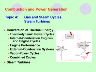
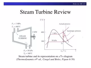
STEAM TURBINE POWER CYCLES. The vast majority of electrical generating plants are variations of vapour power plants in which water is the working fluid. The basic components of a simplified fossil-fuel vapour power plant are shown schematically in the next slide.

E N D
The vast majority of electrical generating plants are variations of vapour power plants in which water is the working fluid. • The basic components of a simplified fossil-fuel vapour power plant are shown schematically in the next slide.
The thermal efficiency of a Rankine Cycle is expressed as The back work ratio for the Rankine power cycle is
Example 1 Steam is the working fluid in an ideal Rankine cycle. Saturated vapour enters the turbine at 8.0 MPa and saturated liquid exits the condenser at a pressure of 0.008 MPa. The net power output of the cycle is 100 MW. Determine for the cycle (a) the thermal efficiency, (b) the back work ratio, (c) the mass flow rate of the steam, in kg/h, (d) the rate of heat transfer, into the working fluid as it passes through the boiler, in MW, (e) the rate of heat transfer, from the condensing steam as it passes through the condenser, in MW, (f) the mass flow rate of the condenser cooling water, in kg/h, if cooling water enters the condenser at 15oC and exits at 35oC.
Effects of Boiler and Condenser Pressures on the Rankine Cycle
Effects of varying operating pressures on the ideal Rankine cycle. (a) Effect of boiler press. (b) Effect of condenser press.
Illustration used to compare the ideal Rankine cycle with the Carnot cycle
Temperature-entropy diagrams showing the effects of turbine and pump irreversibilities
Example 2 Reconsider the vapour power cycle of Example 1, but include in the analysis that the turbine and the pump each have an isentropic efficiency of 85%. Determine for the modified cycle (a) the thermal efficiency, (b) the mass flow rate of steam, in kg/h, for a net power output of 100 MW, (c) the rate of heat transfer into the working fluid as it passes through the boiler, in MW, (d) the rate of heat transfer from the condensing steam as it passes through the condenser, in MW, (e) the mass flow rate of the condenser cooling water, in kg/h, if cooling water enters the condenser at 15oC and exits at 35oC.