Download
1 / 7
70 likes | 80 Views
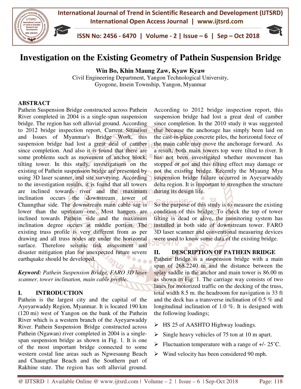
Pathein Suspension Bridge constructed across Pathein River completed in 2004 is a single span suspension bridge. The region has soft alluvial ground. According to 2012 bridge inspection report, Current Situation and Issues of Myanmars Bridge Work, this suspension bridge had lost a great deal of camber since completion. And also it is found that there are some problems such as movement of anchor block, tilting tower. In this study, investigations on the existing of Pathein suspension bridge are presented by using 3D laser scanner, and site surveying. According to the investigation results, it is found that all towers are inclined towards river and the maximum inclination occurs the downstream tower of Chaungthar side. The downstream main cable sag is lower than the upstream one. Most hangers are inclined towards Pathein side and the maximum inclination degree occurs at middle portion. The existing truss profile is very different from as per drawing and all truss nodes are under the horizontal surface. Therefore seismic risk assessment and disaster mitigation plan for unexpected future severe earthquake should be developed. Win Bo | Khin Maung Zaw | Kyaw Kyaw "Investigation on the Existing Geometry of Pathein Suspension Bridge" Published in International Journal of Trend in Scientific Research and Development (ijtsrd), ISSN: 2456-6470, Volume-2 | Issue-6 , October 2018, URL: https://www.ijtsrd.com/papers/ijtsrd18436.pdf Paper URL: http://www.ijtsrd.com/engineering/civil-engineering/18436/investigation-on-the-existing-geometry-of-pathein-suspension-bridge/win-bo<br>

E N D
International Journal of Trend in International Open Access Journal International Open Access Journal | www.ijtsrd.com International Journal of Trend in Scientific Research and Development (IJTSRD) Research and Development (IJTSRD) www.ijtsrd.com ISSN No: 2456 ISSN No: 2456 - 6470 | Volume - 2 | Issue – 6 | Sep 6 | Sep – Oct 2018 Investigation on the Existing Geometry Existing Geometry of Pathein Suspension Bridge Win Bo, Khin Maung Zaw, Kyaw Kyaw Civil Engineering Department, Yangon Technological University, Pathein Suspension Bridge Win Bo, Khin Maung Zaw, Kyaw Kyaw Civil Engineering Department, Yangon Gyogone, Gyogone, Insein Township, Yangon,Myanmar iversity, ABSTRACT Pathein Suspension Bridge constructed across Pathein River completed in 2004 is a single-span suspension bridge. The region has soft alluvial ground to 2012 bridge inspection report, Current Situation and Issues of Myanmar's Bridge Work, this suspension bridge had lost a great deal of camber since completion. And also it is found that there are some problems such as movement of anchor block tilting tower. In this study, investigations on the existing of Pathein suspension bridge are using 3D laser scanner, and site surveying. According to the investigation results, it is found that all towers are inclined towards river and the m inclination occurs the Chaungthar side. The downstream main cable sag is lower than the upstream one. Most hangers are inclined towards Pathein side and the maximum inclination degree occurs at middle portion. The existing truss profile is very different from as per drawing and all truss nodes are under the horizontal surface. Therefore seismic risk assessment and disaster mitigation plan for unexpected future severe earthquake should be developed. Keyword: Pathein Suspension Bridge, FARO 3D laser scanner, tower inclination, main cable profile. I. INTRODUCTION Pathein is the largest city and the capital of the Ayeyarwaddy Region, Myanmar. It is located 190 (120 mi) west of Yangon on the bank of the River which is a western branch of the River. Pathein Suspension Bridge const Pathein (Ngawan) river completed in 2004 is a span suspension bridge as shown in Fig. of the most important bridge connected to some western costal line areas such as Ngwesaung and Chaungthar Beach and the Southern part of Rakhine state. The region has soft alluvial According to 2012 bridge inspection report suspension bridge had lost a great deal of since completion. In the 2010 study it was suggested that because the anchorage has simply been laid on the cast-in-place concrete piles, the horizontal force of the main cable may move the anchorage forward. a result, both main towers top has not been investigated w stopped or not and this tilting effect may damage or not the existing bridge. Recently the Myaung Mya suspension bridge failure occurred in Ayeyarwaddy delta region. It is important to during its design life. So the purpose of this study is to measure the existing condition of this bridge. To check the top of tower tilting is dead or alive, the monitoring system has installed at both side of downstream tower. FAR 3D laser scanner and conventional measuring devices were used to know some data of the existing bridge. II. DESCRIPTION OF PATHEIN BRIDGE Pathein Bridge is a suspensi span of 268.2240 m and the distance between the splay saddle in the anchor and main tower is 86.00 m as shown in Fig. 1. The carriage way consists of two lanes for motorized traffic on the decking of the truss, total width 8.5 m. the headroom for navigation is 33 ft and the deck has a transverse inclination of 0.5 % an longitudinal inclination of 1.0 %. the following loadings; Pathein Suspension Bridge constructed across Pathein According to 2012 bridge inspection report, this suspension bridge had lost a great deal of camber since completion. In the 2010 study it was suggested that because the anchorage has simply been laid on place concrete piles, the horizontal force of the main cable may move the anchorage forward. As towers top were tilted to river. It span suspension bridge. The region has soft alluvial ground. According to 2012 bridge inspection report, Current Situation and Issues of Myanmar's Bridge Work, this suspension bridge had lost a great deal of camber since completion. And also it is found that there are some problems such as movement of anchor block, whether movement has investigations on the stopped or not and this tilting effect may damage or not the existing bridge. Recently the Myaung Mya suspension bridge failure occurred in Ayeyarwaddy delta region. It is important to strengthen the structure existing of Pathein suspension bridge are presented by using 3D laser scanner, and site surveying. According to the investigation results, it is found that all towers are inclined towards river and the maximum inclination occurs the Chaungthar side. The downstream main cable sag is lower than the upstream one. Most hangers are inclined towards Pathein side and the maximum inclination degree occurs at middle portion. The profile is very different from as per drawing and all truss nodes are under the horizontal surface. Therefore seismic risk assessment and disaster mitigation plan for unexpected future severe downstream downstream tower tower of of So the purpose of this study is to measure the existing condition of this bridge. To check the top of tower tilting is dead or alive, the monitoring system has installed at both side of downstream tower. FARO 3D laser scanner and conventional measuring devices were used to know some data of the existing bridge. DESCRIPTION OF PATHEIN BRIDGE ion bridge with a main m and the distance between the the anchor and main tower is 86.00 m 1. The carriage way consists of two lanes for motorized traffic on the decking of the truss, total width 8.5 m. the headroom for navigation is 33 ft and the deck has a transverse inclination of 0.5 % and longitudinal inclination of 1.0 %. It is designed with Bridge, FARO 3D laser scanner, tower inclination, main cable profile. is the largest city and the capital of the . It is located 190 km on the bank of the Pathein which is a western branch of the Ayeyarwaddy ?HS 25 of AASHTO Highway loadings. ?Single heavy vehicles of 75 ton at 10 m apart. ?Fluctuation temperature with a range of +/ ?Wind velocity has been considered 90 mph. HS 25 of AASHTO Highway loadings. nstructed across Pathein (Ngawan) river completed in 2004 is a single- Single heavy vehicles of 75 ton at 10 m apart. Fig. 1. It is one Fluctuation temperature with a range of +/- 25˚C. of the most important bridge connected to some Ngwesaung Beach Wind velocity has been considered 90 mph. r Beach and the Southern part of soft alluvial ground. @ IJTSRD | Available Online @ www.ijtsrd.com www.ijtsrd.com | Volume – 2 | Issue – 6 | Sep-Oct 2018 Oct 2018 Page: 118
International Journal of Trend in Scientific Research and Development (IJTSRD) ISSN: 2456 International Journal of Trend in Scientific Research and Development (IJTSRD) ISSN: 2456 International Journal of Trend in Scientific Research and Development (IJTSRD) ISSN: 2456-6470 Fig. 1.a Elevation of Pathein Suspension Bridge Fig. 1.a Elevation of Pathein Suspension Bridge Fig. 2 Inclined Inclined tower Fig. 1.b Perspective View of Pathein Suspension Bridge Fig. 1.b Perspective View of Pathein Suspension Fig. 3 Inclined hanger Fig. 3 Inclined hanger Fig. 1.c Plan View from Google Earth Fig. 1.c Plan View from Google Earth III. SOME CURRENT CONDITIONS OF PATHEIN BRIDGE The main cables are suspended between two main towers. There may be many reasons tilting the top of tower towards river. As described before, because the region has soft alluvial ground, the horizontal force of the main cable may move concrete blocks and/o tower foundation may rotate due to differential settlement. Moreover, it is due to some construction errors or the backstay cables lengths are the optimum. Most hangers are inclined towards Pathein side and the towers top tilting amounts are same. We can see clearly loss of camber and the unsymmetrical deflection of the main truss of this bridge. SOME CURRENT CONDITIONS OF The main cables are suspended between two main towers. There may be many reasons tilting the top of tower towards river. As described before, because the region has soft alluvial ground, the horizontal force of the main cable may move concrete blocks and/or the tower foundation may rotate due to differential settlement. Moreover, it is due to some construction lengths are longer than the optimum. Most hangers are inclined towards amounts are not same. We can see clearly loss of camber and the unsymmetrical deflection of the main truss of this Fig. 4 Web crippling of Vertical member at Fig. 4 Web crippling of Vertical member at downstream bearing of Chaungthar Side downstream bearing of Chaungthar Side @ IJTSRD | Available Online @ www.ijtsrd.com www.ijtsrd.com | Volume – 2 | Issue – 6 | Sep-Oct 2018 Oct 2018 Page: 119
International Journal of Trend in Scientific Research and Development (IJTSRD) ISSN: 2456 International Journal of Trend in Scientific Research and Development (IJTSRD) ISSN: 2456 International Journal of Trend in Scientific Research and Development (IJTSRD) ISSN: 2456-6470 Fig. 5 Deflection of truss near Tower Fig. 5 Deflection of truss near Tower Fig. 7 Portable data logger Fig. 7 Portable data logger IV. SOME BRIDGE SITE The following devices were used to know the existing condition of Pathein Suspension bridge. They are 1.Monitoring system 2.FARO 3D Laser scanner 3.Digital spirit level 4.1 Monitoring System The main purpose of installing the monitoring system is to check whether the top of tower tilting is dead or alive. In order to monitor the inclination of the main tower, the system has an inclinometer and a portable data logger. The inclinometer is to measure the movement of tower and the data logger is to record the measured data of inclinometer. The monitoring system was installed both downstream towers of Pathein suspension bridge. Fig. 8 shows the plan view of the bridge site and the location of system. The tower movement which is positive or negative direction is also shown. SOME DEVICES DEVICES MEASURED MEASURED AT AT The following devices were used to know the existing condition of Pathein Suspension bridge. They are . The main purpose of installing the monitoring system to check whether the top of tower tilting is dead or In order to monitor the inclination of the main tower, the system has an inclinometer and a portable Fig. 8 Plan view of the direction irection of measurement 4.2 FARO 3D Laser Scanning Process FARO 3D Laser Scanner measurement of Pathein Suspension bridge. It can produce incredibly detailed three of complex environments and large scale geometries. The resulting image is an assembly of millions of 3D measurement points that pro reproduction of existing measurements of using FARO 3D Laser Scanner to measure the detail measurements are described the following chart. FARO 3D Laser Scanning Process is used for detailed to measure the measurement of Pathein Suspension bridge. It can produce incredibly detailed three-dimensional images of complex environments and large scale geometries. The resulting image is an assembly of millions of 3D measurement points that provide an exact digital reproduction of existing measurements of using FARO 3D Laser Scanner to measure the detail measurements are described the movement of tower and the data logger is to record the measured data of inclinometer. The monitoring system was installed both downstream towers of Pathein suspension bridge. Fig. 8 shows the plan view of the bridge site and the location of monitoring system. The tower movement which is positive or conditions. conditions. The The Fig. 6 Inclinometer @ IJTSRD | Available Online @ www.ijtsrd.com www.ijtsrd.com | Volume – 2 | Issue – 6 | Sep-Oct 2018 Oct 2018 Page: 120
International Journal of Trend in Scientific Research and Development (IJTSRD) ISSN: 2456 International Journal of Trend in Scientific Research and Development (IJTSRD) ISSN: 2456 International Journal of Trend in Scientific Research and Development (IJTSRD) ISSN: 2456-6470 The data measured with FARO 3D Laser Scanner are scribed in Table II. Every tower has its own tilting amount. Although the inclinations are different, both downstream towers tilting are more than the upstream one. Moreover, Chaungthar side towers are more The data measured with FARO 3D Laser Scanner are described in Table II. Every tower has its own tilting amount. Although the inclinations are different, both downstream towers tilting are more than the upstream one. Moreover, Chaungthar side towers are more inclined than Pathein side. Fig. 9 FARO 3D Laser Scanner and Scanning Objects RESULTS AND DISCUSSIONS Most of results are based on the monitoring and field measurement. Moreover the data from the ministry of construction such as field measurement data and some as per drawing data discussed. The following portions are discusses in this paper. 1.Main Tower 2.Main cable 3.Hanger 4.Steel Stiffening Truss 5.1 Main Tower The Main Tower are designed with a box 1.9 m x 2.2 m, and made of steel Q345. The height of main tower columns at both sides is 34.43 m. The bottom transverse beam of main tower i prestressing reinforced concrete, and have a box section of 2.5 m x 2.0 m. Table I and Table II shows the tower top tilting amount measured from Ministry of Construction and measured with FARO 3D Laser Scanner. All towers are inclined to longitud direction and towards river. TABLEI.MAINTOWERINCLINATION Measured Date (mm) 20-6-2016 -240 14-10-2016 -225 TABLEII.MAINTOWERINCLINATION (MEASUREDDATE6.4.17) Side Location (mm) Upstream -197 Downstream -213 Average -205 The data contained in Table I are collected from Ministry of construction measured in 2016. Although the two measurement values at Pathein side are much closed, Chaungthar side values are quite different. closed, Chaungthar side values are quite different. Fig. 9 FARO 3D Laser Scanner and Scanning V. Most of results are based on the monitoring and field measurement. Moreover the data from the ministry of construction such as field measurement data and some as per drawing data discussed. The following portions DISCUSSIONS Fig. 10 Tower inclination at Chaungthar side due to temperature inclination at Chaungthar side due to temperature The Main Tower are designed with a box-section of 1.9 m x 2.2 m, and made of steel Q345. The height of main tower columns at both sides is 34.43 m. The bottom transverse beam of main tower is made of prestressing reinforced concrete, and have a box- section of 2.5 m x 2.0 m. Table I and Table II shows the tower top tilting amount measured from Ministry of Construction and measured with FARO 3D Laser Scanner. All towers are inclined to longitudinal Fig. 11 Tower inclination and Temperature at Fig. 11 Tower inclination and Temperature at Chaungthar side Chaungthar side Fig 10 and Fig 11 are the monitoring results for downstream tower of Chaungthar side from November 2017 to April 2018. Fig 10 shows the inclination degree of tower due to temperature fluctuation. The blue sports represent for the inclination degree parallel to bridge axis direction and the red sports are for perpendicular to bridge axis direction. Fig 11 describes the hourly recorded data of temperature, inclination degree parallel to bridge axis direction and perpendicular to bridge axis direction. According to these recorded data, no significant amount of tower inclination degree can be seen. The inclination degrees are very small and these a the effect of temperature fluctuation. So we can conclude that the tower is stable or it is not alive. 5.2 Main Cable The main cables adopt high tensile strength galvanized steel wires. It is parallel wire strand type. galvanized steel wires. It is parallel wire strand type. Fig 10 and Fig 11 are the monitoring results for downstream tower of Chaungthar side from November 2017 to April 2018. Fig 10 shows the nation degree of tower due to temperature fluctuation. The blue sports represent for the inclination degree parallel to bridge axis direction and the red sports are for perpendicular to bridge axis direction. Fig 11 describes the hourly recorded data of mperature, inclination degree parallel to bridge axis direction and perpendicular to bridge axis direction. INCLINATION Chaungthar Pathein Side Chaungthar Side Side (mm) +165 +310 INCLINATION 6.4.17) Chaungthar Pathein Side Chaungthar Side Side (mm) +281 +291 +286 According to these recorded data, no significant amount of tower inclination degree can be seen. The inclination degrees are very small and these are due to the effect of temperature fluctuation. So we can conclude that the tower is stable or it is not alive. The data contained in Table I are collected from Ministry of construction measured in 2016. Although the two measurement values at Pathein side are much The main cables adopt high tensile strength @ IJTSRD | Available Online @ www.ijtsrd.com www.ijtsrd.com | Volume – 2 | Issue – 6 | Sep-Oct 2018 Oct 2018 Page: 121
International Journal of Trend in Scientific Research and Development (IJTSRD) ISSN: 2456 International Journal of Trend in Scientific Research and Development (IJTSRD) ISSN: 2456 International Journal of Trend in Scientific Research and Development (IJTSRD) ISSN: 2456-6470 The diameter of steel wire is 5.1 mm after galvanized. There are 37 bundles of steel wire in the main cable and each bundle consists of 61 number of steel wires. As describe the previous section, each tower has its own tilting amount. Because of this differential tilting, the existing main cables profile is unsymmetrical. Moreover these two main cables profile are different from its original, as per drawing, profile. from its original, as per drawing, profile. is 5.1 mm after galvanized. There are 37 bundles of steel wire in the main cable and each bundle consists of 61 number of steel wires. As describe the previous section, each tower has its own tilting amount. Because of this differential tilting, existing main cables profile is unsymmetrical. Moreover these two main cables profile are different Chaungthar Side Pathein Side Fig. 13.b Downstream Cable length Fig. 13.b Downstream Cable length TABLEIV.TOTALLENGTH Drawing LENGTHOFMAINCABLE Measured length (m) length (m) Measured Difference (m) Location length (m) 276.103 276.103 Upstream Downstream 275.940 275.981 - 0.150 - 0.122 The measured main cables length and as per drawing main cables length are shown in Fig. 13.a and Fig. 13.b. Fig. 13.a is for the upstream main cable length and Fig. 13.b is for downstream. The main cables difference near towers are noticeable and others are nearly the same length. The maximum segment length difference is 1.009 m at the nearest segment of Pathein side tower for upstream and 0.937 m at the nearest segment of Chaungthar side tower for downstream. The total upstream main cable length between the towers is 276.94 m and the downstream is 275.981 m. The length difference is 0.06% for upstream and 0.044% for downstream. Both upstream and downstream main cable Table 4. 5.3Hanger The hangers are parallel wire strand type. There is one suspender per suspending point at 5 m apart. The suspenders are designed with high tensile strength galvanized steel wires. There are 61 numbers of 5 mm diameter strand wire for one hanger. Pathein suspension bridge was inspected in 2010 and 2011 with JAPAN-Myanmar Bridge engineer. It was reported some hangers are inclined and most of them are inclined towards Pathein side. But few hangers are towards Chaungthar side. The reason of these hanger inclination problem was not reported. Hangers’ inclinations were measured with electronic spirit level and FARO 3D Laser Scanner. The first one is direct measurement and it was done in February 2017. The second is not a direct measurement and the processes are described in chart measurement and the processes are described in chart measured main cables length and as per drawing main cables length are shown in Fig. 13.a and Fig. 13.b. Fig. 13.a is for the upstream main cable length and Fig. 13.b is for downstream. The main cables difference near towers are noticeable and others are early the same length. The maximum segment length difference is 1.009 m at the nearest segment of Pathein side tower for upstream and 0.937 m at the nearest segment of Chaungthar side tower for downstream. The total upstream main cable length owers is 276.94 m and the downstream is 275.981 m. The length difference is 0.06% for upstream and 0.044% for downstream. Both upstream and downstream main cable lengths are shown in Fig. 12 Main Cable Profiles Fig. 12 Main Cable Profiles TABLEIII.MAXIMUMSAG DIFFERENCE Drawing Sag (m) Upstream 28.737 Downstream 28.737 SAGAND Measured Sag (m) 29.37 29.50 Difference (m) - 0.633 - 0.763 Location Fig. 12 shows the two main cables profile, the existing main cable profile and profile as per drawing. The existing profile is lower than as per drawing profile. Table III describes the maximum sag of main cables profile and the difference of these two pro From Table II, it can be clearly seen that the downstream towers are more inclined than the upstream. This is the reason why the downstream main cable sag is lower than the upper one. Fig. 12 shows the two main cables profile, the existing main cable profile and profile as per drawing. The existing profile is lower than as per drawing profile. Table III describes the maximum sag of main cables profile and the difference of these two profiles. From Table II, it can be clearly seen that the downstream towers are more inclined than the upstream. This is the reason why the downstream main cable sag is lower than the upper one. The hangers are parallel wire strand type. There is one suspender per suspending point at 5 m apart. The suspenders are designed with high tensile strength galvanized steel wires. There are 61 numbers of 5 mm diameter strand wire for one hanger. Pathein suspension bridge was inspected in 2010 and 2011 Myanmar Bridge engineer. It was reported some hangers are inclined and most of them are inclined towards Pathein side. But few hangers are towards Chaungthar side. The reason of these hanger inclination problem was not reported. measured with electronic spirit level and FARO 3D Laser Scanner. The first one is direct measurement and it was done in February 2017. The second is not a direct Pathein Side Chaungthar Side Fig. 13.a Upstream Cable length length @ IJTSRD | Available Online @ www.ijtsrd.com www.ijtsrd.com | Volume – 2 | Issue – 6 | Sep-Oct 2018 Oct 2018 Page: 122
International Journal of Trend in Scientific Research and Development (IJTSRD) ISSN: 2456 International Journal of Trend in Scientific Research and Development (IJTSRD) ISSN: 2456 International Journal of Trend in Scientific Research and Development (IJTSRD) ISSN: 2456-6470 1. The scanning object processing was 2017. The finalization was done with AutoCAD software. taken in April measured results used FARO 3D laser scanner. The direct measured results used the electronic spirit level is shown in Fig. 14.b. From these two figures, the hangers near tower and the middle hangers are more inclined than others. Negative sign means the hangers are inclined towards Chaungthar side. The towers at Chaungthar side are more inclined than the tower at Pathein side. This is one of the reasons why the most hangers are inclined towards Pathein side. Fig. 14.c is the hanger inclination degree measured with FARO 3D Laser Scanner and electronic spirit level. Although the measured results are different, their lines shape are e hanger length difference between the measured length and as per drawing length. All existing hangers are longer than as per drawing length. This may be one of the factors that this suspension bridge steel truss vertical profile has . The blue line represents upstream hangers’ length difference and the red line is measured results used FARO 3D laser scanner. The direct measured results used the electronic spirit level is shown in Fig. 14.b. From these two figures hangers near tower and the middle hangers are more inclined than others. Negative sign means the hangers are inclined towards Chaungthar side. The towers at Chaungthar side are more inclined than the tower at Pathein side. This is one of the reasons hangers are inclined towards Pathein side. Fig. 14.c is the hanger inclination degree measured with FARO 3D Laser Scanner and electronic spirit level. Although the measured results are different, their lines shape are similar. Fig. 14 d. is the hanger length difference between the measured length and as per drawing length. All existing hangers are longer than as per drawing length. This may be one of the factors that this suspension bridge steel truss vertical profile has unusual deformed shape. The blue line represents upstream hangers’ length difference and the red line is for downstream. 5.4 Steel Stiffing Truss Main girder is a steel stiffening truss using "warren'' girder trusses. The truss is 3m high and 5m long per bay. The end bays are 5.5 m long. A bay is taken as a unit to the upper and bottom chord. The total length of truss between bearings is 266.00 m. The truss has a vertical curve and it is for camber and its radius is 14000 m. The steel structures have the bottom bracing for wind stability and they are designed with H section. To increase the stability of main truss, all gussets on upper chords have transverse bracing. Ministry of Construction have checked regularly to know the condition of this bridge especially the inclination of towers and the vertical profile of steel stiffening truss. Moreover variations of the vertical profile were recorded during a load test program tested in June 2016. It was done with two dump trucks weighing 20 tons each and the total weight The trucks were placed at three locations on the bridge and Fig. 15 is one of the locations of trucks during load test program. 2017. The finalization was done with AutoCAD Fig. 14.a Hanger inclination measured with FARO 3D Laser Scanner Fig. 14.a Hanger inclination measured with FARO 3D Fig. 14.b Hanger inclination measured with electronic spirit level Fig. 14.b Hanger inclination measured with electronic Main girder is a steel stiffening truss using "warren'' girder trusses. The truss is 3m high and 5m long per e 5.5 m long. A bay is taken as a unit to the upper and bottom chord. The total length of truss between bearings is 266.00 m. The truss has a vertical curve and it is for camber and its radius is 14000 m. The steel structures have the bottom bracing nd stability and they are designed with H section. To increase the stability of main truss, all gussets on upper chords have transverse bracing. Ministry of Construction have checked regularly to know the condition of this bridge especially the inclination of towers and the vertical profile of steel stiffening truss. Moreover variations of the vertical profile were recorded during a load test program tested in June 2016. It was done with two dump trucks weighing 20 tons each and the total weight is 40 tons. The trucks were placed at three locations on the bridge and Fig. 15 is one of the locations of trucks Fig. 14.c Hanger inclination measured with FA Laser Scanner and electronic spirit level Fig. 14.c Hanger inclination measured with FARO 3D Laser Scanner and electronic spirit level Fig. 14.d Hanger length difference Fig. 14.d Hanger length difference Fig. 14.a and Fig 14.b show the hanger inclination degree of Pathein suspension bridge. Fig. 14.a is the degree of Pathein suspension bridge. Fig. 14.a is the Fig. 14.a and Fig 14.b show the hanger inclination Fig. 15 Location of trucks during load test at L/4 Span Fig. 15 Location of trucks during load test at L/4 Span @ IJTSRD | Available Online @ www.ijtsrd.com www.ijtsrd.com | Volume – 2 | Issue – 6 | Sep-Oct 2018 Oct 2018 Page: 123
International Journal of Trend in Scientific Research and Development (IJTSRD) ISSN: 2456 International Journal of Trend in Scientific Research and Development (IJTSRD) ISSN: 2456 International Journal of Trend in Scientific Research and Development (IJTSRD) ISSN: 2456-6470 CONCLUSION Based on these investigation results, although the inclinations of towers are different, both downstream towers tilting are more than the upstream one. Moreover, both towers at Chaungthar side are more inclined than Pathein side. This is the reason why the downstream main cable sag is greater than the upstream one and most of hangers are inclined towards Pathein side. The maximum hanger inclination is 4.16 degrees and it is occurred at mid- span. The existing truss deformation is unusual pattern and it may be due to the differential of tower. Measuring the existing geometry is one of the essential processes to model and analyze the structures. The existing structural performance of this bridge can be assessed using these investigative data. After assessing ormances, the required action plan can be VI. Based on these investigation results, inclinations of towers are different, both downstream towers tilting are more than the upstream one. Moreover, both towers at Chaungthar side are more inclined than Pathein side. This is the reason why the downstream main cable sag is greater upstream one and most of hangers are inclined towards Pathein side. The maximum hanger inclination is 4.16 degrees and it is occurred at mid span. The existing truss deformation is unusual pattern and it may be due to the differential inclination of tower. Measuring the existing geometry is one of the essential processes to model and analyze the structures. The existing structural performance of this bridge can be assessed using these investigative data. After assessing performances, the required action plan can be proposed confidentially. ACKNOWLEDGMENT The authors are thankful to the Ministry of Construction for providing the required data in this study. REFERENCES 1.Public Works. 2004. Design Drawings of Pathein Suspension Bridge. 2.AASHTO. 2002. Standard Specifications for Highway Bridge. 17th ed. American Association of State Highway and Transportation Officials. 3.FARO® Laser Scanner Focus3D Manual October 2011. Fig. 16 Location of trucks during load test at 3L/4 Span Fig. 16 Location of trucks during load test at 3L/4 Fig. 16 Deflection of Pathein suspension Bridge Fig. 16 Deflection of Pathein suspension Bridge the the existing existing structural structural Fig. 16 shows the vertical profile of steel stiffening truss of Pathein suspension bridge. The blue line is as per drawing profile of the truss and the maximum camber is + 642.15 mm at the mid-span construction was completed in 2004. The yellow colour line is the truss profile measured by ministry of construction survey team in September 2011. At that time, the road surface was under the horizontal line. The maximum deflection is -104.233 mm and that point is 33 m from Pathein side tower. Meanwhile the mid-span deflection was -74.305 mm. at the end of year 2011 measurement, the maximum deflection became - 224.334 mm and mid-span deflection was 84.683 mm. The deflection was gradually and it was found the worst condition in July 2016 measurement. But in October 2016 measurement, recovery deflection was occurred. The red line is the deflection measured with FARO 3D laser scanner in April 2017. According to that measurement, the maximum is -253.49 mm near Chaungthar side tower and mid-span deflection is -109.85 mm. Fig. 16 shows the vertical profile of steel stiffening truss of Pathein suspension bridge. The blue line is as s and the maximum of bridge. The The authors are thankful to the Ministry of Construction for providing the required data in this construction was completed in 2004. The yellow colour line is the truss profile measured by ministry of construction survey team in September 2011. At that time, the road surface was under the horizontal line. .233 mm and that Design Drawings of Pathein point is 33 m from Pathein side tower. Meanwhile the 74.305 mm. at the end of year 2011 measurement, the maximum deflection Standard Specifications for ed. American Association of span deflection was - State Highway and Transportation Officials. 84.683 mm. The deflection was gradually increased and it was found the worst condition in July 2016 measurement. But in October 2016 measurement, recovery deflection was occurred. The red line is the deflection measured with FARO 3D laser scanner in April 2017. According to that measurement, the 253.49 mm near Chaungthar side tower Laser Scanner Focus3D Manual, 4.Japan Infrastructure Partners (JIP) Situation and Issues ofMyanmar's Bridge September 2012. Japan Infrastructure Partners (JIP), Current Myanmar's BridgeWork, @ IJTSRD | Available Online @ www.ijtsrd.com www.ijtsrd.com | Volume – 2 | Issue – 6 | Sep-Oct 2018 Oct 2018 Page: 124