Computer Elements
280 likes | 507 Views
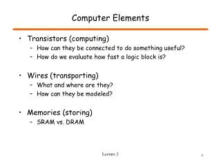
Computer Elements. Transistors (computing) How can they be connected to do something useful? How do we evaluate how fast a logic block is? Wires (transporting) What and where are they? How can they be modeled? Memories (storing) SRAM vs. DRAM. What Comes out of the Fab?.

Computer Elements
E N D
Presentation Transcript
Computer Elements • Transistors (computing) • How can they be connected to do something useful? • How do we evaluate how fast a logic block is? • Wires (transporting) • What and where are they? • How can they be modeled? • Memories (storing) • SRAM vs. DRAM Lecture 2
What Comes out of the Fab? Lecture 2
The Mighty Transistor! Lecture 2
D G S Transistor As a Switch • Ideal Voltage Controlled Switch • Three terminals • Gate • Drain • Source D G S VG = 0 VG = Vdd Lecture 2
Abstractions in Logic Design • In physical world • Voltages, Currents • Electron flow • In logical world - abstraction • V < Vlo “0” = FALSE • V > Vhi “1” = TRUE • In between - forbidden • Simplify design problem voltage Vdd “1” Vhi “?” Vlo “0” 0v Lecture 2
Basic Technology: CMOS • CMOS: Complementary Metal Oxide Semiconductor • NMOS (N-Type Metal Oxide Semiconductor) transistors • PMOS (P-Type Metal Oxide Semiconductor) transistors • NMOS Transistor • Apply a HIGH (Vdd) to its gateturns the transistor into a “conductor” • Apply a LOW (GND) to its gateshuts off the conduction path • PMOS Transistor • Apply a HIGH (Vdd) to its gate shuts off the conduction path • Apply a LOW (GND) to its gate turns the transistor into a “conductor” Vdd = (2.5V) GND = 0v Vdd = (2.5V) GND = 0v Lecture 2 Slide courtesy of D. Patterson
Open Charge Out Open Discharge Basic Components: CMOS Inverter Vdd • Inverter Operation Symbol Circuit PMOS In Out In Out NMOS Vout Vdd Vdd Vdd Vdd Vin Vdd Lecture 2 Slide courtesy of D. Patterson
Composition of Transistors • Logic Gates • Inverters, And, Or, arbitrary • Buffers (drive large capacitances, long wires, etc.) • Memory elements • Latches, registers, SRAM, DRAM NOR inverter NAND Lecture 2
A B Out A B Out A Out 0 0 1 A Out 0 0 1 0 1 1 0 1 0 B B 1 0 1 1 0 0 1 1 0 1 1 0 Vdd Vdd A Out B B Out A Basic Components: CMOS Logic Gates NOR Gate NAND Gate Lecture 2 Slide courtesy of D. Patterson
Vdd Vdd A Out B B Out A Gate Comparison • If PMOS transistors is faster: • It is OK to have PMOS transistors in series • NOR gate is preferred • NOR gate is preferred also if H -> L is more critical than L -> H • If NMOS transistors is faster: • It is OK to have NMOS transistors in series • NAND gate is preferred • NAND gate is preferred also if L -> H is more critical than H -> L NOR Gate NAND Gate Lecture 2 Slide courtesy of D. Patterson
The Ugly Truth • Transistors are not ideal switches! • Gate Capacitance (Cg) • S-D resistance (R) - also Rp 2*Rn • Drain capacitance • Issues • Delay - actually takes real time to turn transistors on and off • Power/Energy (static versus dynamic power) • Noise (from transistors, power rails) • But - we can change transistor size • Increase Cg, but decrease R Lecture 2
In Out Ideal (CS) versus Reality (EE) • When input 0 -> 1, output 1 -> 0 but NOT instantly • Output goes 1 -> 0: output voltage goes from Vdd (5v) to 0v • When input 1 -> 0, output 0 -> 1 but NOT instantly • Output goes 0 -> 1: output voltage goes from 0v to Vdd (5v) • Voltage does not change instantaneously Voltage Vout 1 => Vdd Vin 0 => GND Time Lecture 2 Slide courtesy of D. Patterson
Fluid Timing Model Level (V) = Vdd • Water <-> Electrical Charge Tank Capacity <-> Capacitance (C) • Water Level <-> Voltage Water Flow <-> Charge Flowing (Current) • Size of Pipes <-> Strength of Transistors (G) • Time to fill up the tank ~ C / G Vdd Tank Level (Vout) SW1 SW1 SW2 Sea Level (GND) Vout Cout SW2 Reservoir Tank (Cout) Bottomless Sea Resistance R = 1/G Lecture 2 Slide courtesy of D. Patterson
Vdd Vin V1 Vout Vout Cout V1 Vout Series Connection Vdd • Total Propagation Delay = Sum of individual delays = d1 + d2 • Capacitance C1 has two components: • Capacitance of the wire connecting the two gates • Input capacitance of the second inverter Vin V1 G1 G2 G1 G2 Voltage C1 Vdd Vin Vdd/2 d1 d2 GND Time Lecture 2 Slide courtesy of D. Patterson
Review: Calculating Delays • Sum delays along serial paths • Delay (Vin -> V2) ! = Delay (Vin -> V3) • Delay (Vin -> V2) = Delay (Vin -> V1) + Delay (V1 -> V2) • Delay (Vin -> V3) = Delay (Vin -> V1) + Delay (V1 -> V3) • Critical Path = The longest among the N parallel paths • C1 = Wire C + Cin of Gate 2 + Cin of Gate 3 Vdd Vdd Vin V1 V2 Vin V1 V2 G1 G2 C1 V3 Vdd V3 G3 Lecture 2 Slide courtesy of D. Patterson
CLK CLK Q D Q D Q Q D D OUT IN Q CLK CLK CLK Clocking and Clocked Elements • Typical Clock • 1Hz = 1 cycle per second period (cycle time) • Transparent Latch CLK=0, Q=oldQ CLK=1, Q=D • Edge Triggered Flip-Flop Lecture 2
Storage Elements Timing Model • Setup Time: Input must be stable BEFORE the trigger clock edge • Hold Time: Input must REMAIN stable after the trigger clock edge • Clock-to-Q time: • Output cannot change instantaneously at the trigger clock edge • Similar to delay in logic gates, two components: • Internal Clock-to-Q • Load dependent Clock-to-Q Clk Setup Hold D Q D Don’t Care Don’t Care Clock-to-Q Q Unknown Lecture 2 Slide courtesy of D. Patterson
Clk . . . . . . . . . . . . Combinational Logic Clocking Methodology • All storage elements are clocked by the same clock edge • The combination logic block’s: • Inputs are updated at each clock tick • All outputs MUST be stable before the next clock tick Lecture 2 Slide courtesy of D. Patterson
. . . . . . . . . . . . Critical Path & Cycle Time • Critical path: the slowest path between any two storage devices • Cycle time is a function of the critical path • must be greater than: • Clock-to-Q + Longest Path through the Combination Logic + Setup Clk Lecture 2 Slide courtesy of D. Patterson
Tricks to Reduce Cycle Time • Reduce the number of gate levels A A B B C C D D • Pay attention to loading • One gate driving many gates is a bad idea • Avoid using a small gate to drive a long wire • Use multiple stages to drive large load INV4x Clarge INV4x Lecture 2 Slide courtesy of D. Patterson
Wires • Limiting Factor • Density • Speed • Power • 3 models for wires (model to use depends on switching frequency) • Short • Lossless • Lossy Lecture 2
Wire Density • Communication constraints • Must be able to move bits to/from storage and computation elements • Example: 9 ported register file 32x64 9 ported Register File ? Lecture 2
Chip Level Lecture 2
Memory • Moves information in time (wires move it in space) • Provides state • Requires energy to change state • Feedback circuit - SRAM • Capacitors – DRAM • Magnetic media - disk • Required for memories • Storage medium • Write mechanism • Read mechanism 4Gb DRAM Die Lecture 2
Technology Scaling Trends • CPU Transistor density – 60% per year • CPU Transistor speed – 15% per year • DRAM density – 60% per year • DRAM speed – 3% per year • On-chip wire speed – decreasing relative to transistors (witness the Pentium 4 pipeline) • Off-chip pin bandwidth – increasing, but slowly • Power – approaching costs limits • P = CV2f + IleakV • All of these factors affect the end system architecture Lecture 2
Summary • Logic Transistors + Wires + Storage = Computer! • Transistors • Composable switches • Electrical considerations • Delay from parasitic capacitors and resistors • Power (P = CV2f) • Wires • Becoming more important from delay and BW perspective • Memories • Density, Access time, Persistence, BW Lecture 2