Download
1 / 46
1.72k likes | 3.23k Views
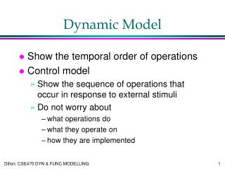
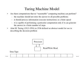
Dynamic Model of Induction Machine. MEP 1522 ELECTRIC DRIVES. In an electric drive system, the machine is part of the control system elements . WHY NEED DYNAMIC MODEL?. To be able to control the dynamics of the drive system, dynamic behavior of the machine need to be considered.

E N D
Dynamic Model of Induction Machine MEP 1522 ELECTRIC DRIVES
In an electric drive system, the machine is part of the control system elements WHY NEED DYNAMIC MODEL? • To be able to control the dynamics of the drive system, dynamic behavior of the machine need to be considered • Dynamic behavior of of IM can be described using dynamic model of IM
Dynamic model – complex due to magnetic coupling between stator phases and rotor phases WHY NEED DYNAMIC MODEL? • Coupling coefficients vary with rotor position – rotor position vary with time • Dynamic behavior of IM can be described by differential equations with time varying coefficients
Magnetic axis of phase B ibs a b’ c’ Magnetic axis of phase A ias b c Simplified equivalent stator winding ics a’ Magnetic axis of phase C DYNAMIC MODEL, 3-PHASE MODEL
stator, b rotor, a r rotor, b stator, a rotor, c stator, c DYNAMIC MODEL – 3-phase model
Let’s look at phase a Flux that links phase a is caused by: DYNAMIC MODEL – 3-phase model • Flux produced by winding a • Flux produced by winding b • Flux produced by winding c
Flux produced by winding b • Flux produced by winding c Let’s look at phase a DYNAMIC MODEL – 3-phase model The relation between the currents in other phases and the flux produced by these currents that linked phase a are related by mutual inductances
Mutual inductance between phase a of stator and phase a of rotor Mutual inductance between phase a and phase c of stator Mutual inductance between phase a and phase b of stator Mutual inductance between phase a of stator and phase b of rotor Mutual inductance between phase a of stator and phase c of rotor Let’s look at phase a DYNAMIC MODEL – 3-phase model
vabcs = Rsiabcs + d(abcs)/dt - stator voltage equation DYNAMIC MODEL – 3-phase model vabcr = Rrriabcr + d(abcr)/dt -rotor voltage equation • abcs flux (caused by stator and rotor currents) that links stator windings • abcr flux (caused by stator and rotor currents) that links rotor windings
DYNAMIC MODEL – 3-phase model Flux linking stator winding due to stator current Flux linking stator winding due to rotor current
Similarly we can write flux linking rotor windings caused by rotor and stator currents: DYNAMIC MODEL – 3-phase model Flux linking rotor winding due to rotor current Flux linking rotor winding due to stator current
Combining the stator and rotor voltage equations, DYNAMIC MODEL – 3-phase model p is the derivative operator , i.e. p = d/dt
DYNAMIC MODEL – 3-phase model Magnetic axis of winding y x y Windings x and y, with Nx and Ny number of turns, separated by α Magnetic axis of winding x y’ x’ It can be shown that the mutual inductance between winding x and y is
DYNAMIC MODEL – 3-phase model • To get self inductance for phase a of the stator let Nx = Ny = Ns and α= 0 • If we consider the leakage flux, we can write the self inductance of phase a of the stator Las = Lam + Lls • Las Self inductance of phase a • Lam Magnetizing inductance of phase a • Lls Leakage inductance of phase a
DYNAMIC MODEL – 3-phase model Due to the symmetry of the windings, Lam = Lbm = Lcm , Hence Las = Lbs = Lcs = Lms + Lls • The magnetizing inductance Lms, accounts for the flux produce by the respective phases, crosses the airgap and links other windings • The leakage inductance Lls, accounts for the flux produce by the respective phases, but does not cross the airgap and links only itself
DYNAMIC MODEL – 3-phase model • It can be shown that the mutual inductance between stator phases is given by:
DYNAMIC MODEL – 3-phase model The mutual inductances between stator phases can be written in terms of magnetising inductances
DYNAMIC MODEL – 3-phase model Self inductance between rotor windings is when Nx = Ny = Nr and α= 0 • The mutual inductances between rotor phases can be written in terms of stator magnetising inductances
The mutual inductances between the stator and rotor windings depends on rotor position DYNAMIC MODEL – 3-phase model Self inductance between phase a of rotor and phase a of stator is when Nx = Ns ,Ny = Nr and α= θr
The mutual inductances between the stator and rotor windings depends on rotor position DYNAMIC MODEL – 3-phase model
DYNAMIC MODEL – 3-phase model stator, b rotor, a r rotor, b stator, a rotor, c stator, c
It is easier to look on dynamic of IM using two-phase model. This can be constructed from the 3-phase model using Park’s transformation DYNAMIC MODEL, 2-PHASE MODEL Two-phase equivalent Three-phase There is NO magnetic coupling between phases There is magnetic coupling between phases
stator, q r rotating rotor, r rotor, stator, d Two-phase equivalent • It is easier to look on dynamic of IM using two-phase model. This can be constructed from the 3-phase model using Parks transformation DYNAMIC MODEL – 2-phase model stator, b rotating r rotor, a r rotor, b stator, a rotor, c Three-phase stator, c
stator, q r rotating rotor, r rotor, stator, d Two-phase equivalent • It is easier to look on dynamic of IM using two-phase model. This can be constructed from the 3-phase model using Parks transformation DYNAMIC MODEL – 2-phase model However coupling still exists between stator and rotor windings
All the 3-phase quantities have to be transformed to 2-phase quantities DYNAMIC MODEL – 2-phase model • In general if xa, xb, and xc are the three phase quantities, the space phasor of the 3 phase systems is defined as: , where a = ej2/3
q d • All the 3-phase quantities have to be transformed into 2-phase quantities DYNAMIC MODEL – 2-phase model
The transformation is given by: DYNAMIC MODEL – 2-phase model For isolated neutral, ia + ib + ic = 0, i.e. io =0 idqo = Tabc iabc The inverse transform is given by: iabc = Tabc-1idqo
2-phase vdq = Rsidq + d(dq)/dt v = Rrri + d( )/dt stator, q r rotating rotor, r rotor, stator, d IM equations : 3-phase vabcs = Rsiabcs + d(abcs)/dt DYNAMIC MODEL – 2-phase model vabcr = Rrriabcr + d(abr)/dt
dq vdq = Rsidq + d(dq)/dt Express in stationary frame DYNAMIC MODEL – 2-phase model v = Rri + d( )/dt Express in rotating frame where,
Note that: Ldq = Lqd = 0 L = L = 0 DYNAMIC MODEL – 2-phase model Ldd = Lqq L = L The mutual inductance between stator and rotor depends on rotor position: Ld = Ld = Lsr cos r Lq = Lq = Lsr cos r Ld = Ld = - Lsr sin rLq = Lq = Lsr sin r
stator, q r rotating rotor, r rotor, stator, d DYNAMIC MODEL – 2-phase model Ld = Ld = Lsr cos r Lq = Lq = Lsr cos r Ld = Ld = - Lsr sin rLq = Lq = Lsr sin r
In matrix form this an be written as: DYNAMIC MODEL – 2-phase model • The mutual inductance between rotor and stator depends on rotor position
stator, q rotor, q r stator, d rotor, d Both stator and rotor rotating or stationary DYNAMIC MODEL – 2-phase model The mutual inductance can be made independent from rotor position by expressing both rotor and stator in the same reference frame, e.g. in the stationary reference frame Magnetic path from stator linking the rotor winding independent of rotor position mutual inductance independent of rotor position
In rotating frame this can be written as: In stationary frame it be written as: qs ir r irq r ds ird DYNAMIC MODEL – 2-phase model How do we express rotor current in stator (stationary) frame? is known as the space vector of the rotor current
If the rotor quantities are referred to stator, the following can be written: DYNAMIC MODEL – 2-phase model Lm, Lr are the mutual and rotor self inductances referred to stator, and Rr’ is the rotor resistance referred to stator Ls = Ldd is the stator self inductance Vrd, vrq, ird, irq are the rotor voltage and current referred to stator
DYNAMIC MODEL – 2-phase model It can be shown that in a reference frame rotating at g, the equation can be written as:
IM can be compactly written using space vectors: DYNAMIC MODEL Space vectors All quantities are written in general reference frame
Product of voltage and current conjugate space vectors: DYNAMIC MODEL Torque equation It can be shown that for ias + ibs + ics = 0,
If and DYNAMIC MODEL Torque equation
Power associated with g – upon expansion gives zero Power Losses in winding resistance Mech power Rate of change of stored magnetic energy The IM equation can be written as: DYNAMIC MODEL Torque equation The input power is given by:
DYNAMIC MODEL Torque equation We know that m = r / (p/2),
but DYNAMIC MODEL Torque equation
Re-arranging with stator and rotor currents as state space variables: DYNAMIC MODEL Simulation The torque can be expressed in terms of stator and rotor currents: