Download
1 / 41
1.87k likes | 5.82k Views
Introduction to Beam Theory. Area Moments of Inertia, Deflection, and Volumes of Beams. What is a Beam?. Horizontal structural member used to support horizontal loads such as floors, roofs, and decks. Types of beam loads Uniform Varied by length Single point Combination.

E N D
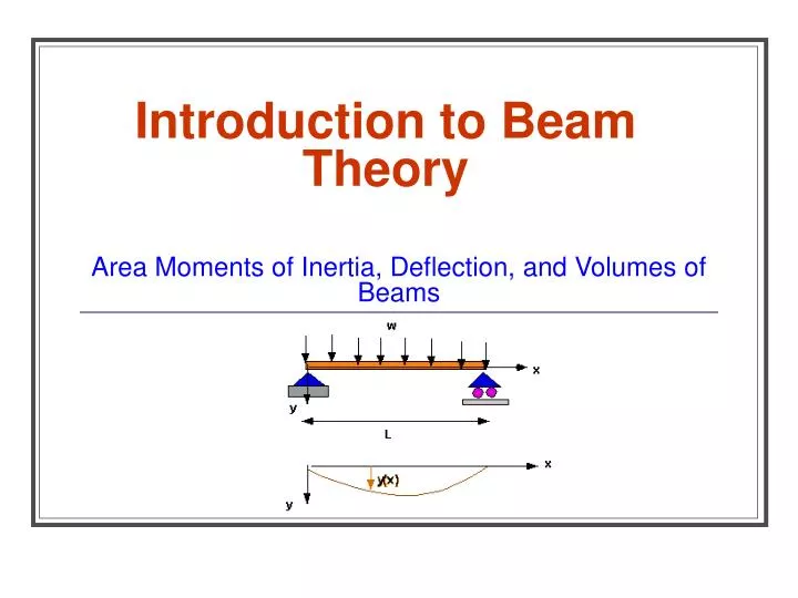
Introduction to Beam Theory Area Moments of Inertia, Deflection, and Volumes of Beams
What is a Beam? • Horizontal structural member used to support horizontal loads such as floors, roofs, and decks. • Types of beam loads • Uniform • Varied by length • Single point • Combination
Common Beam Shapes Hollow Box Solid Box I Beam H Beam T Beam
Web Flanges Web Flanges Beam Terminology • The parallel portions on an I-beam or H-beam are referred to as the flanges. The portion that connects the flanges is referred to as the web.
Support Configurations Source: Statics (Fifth Edition), Meriam and Kraige, Wiley
Concentrated Load Load and Force Configurations Distributed Load Source: Statics (Fifth Edition), Meriam and Kraige, Wiley
L Beam Geometry • Consider a simply supported beam of length, L. • The cross section is rectangular, with width, b, and height, h. h b
Y - Axis h/2 X - Axis h/2 b/2 b/2 Beam Centroid • An area has a centroid, which is similar to a center of gravity of a solid body. • The centroid of a symmetric cross section can be easily found by inspection. X and Y axes intersect at the centroid of a symmetric cross section, as shown on the rectangular cross section. Centroid
Area Moment of Inertia (I) • Inertia is a measure of a body’s ability to resist movement, bending, or rotation • Moment of inertia (I) is a measure of a beam’s • Stiffness with respect to its cross section • Ability to resist bending • As Iincreases, bending decreases • As I decreases, bending increases • Units of I are (length)4, e.g. in4, ft4, or cm4
I for Common Cross-Sections • I can be derived for any common area using calculus. However, moment of inertia equations for common cross sections (e.g., rectangular, circular, triangular) are readily available in math and engineering textbooks. • For a solid rectangular cross section, • b is the dimension parallel to the bending axis • h is the dimension perpendicular to the bending axis h X-axis (passing through centroid) b
P h = 1.00” X-Axis Y-Axis b = 0.25” Which Beam Will Bend (or Deflect) the Most About the X-Axis? P X-Axis h = 0.25” Y-Axis b = 1.00”
Y-Axis h = 1.00” X-Axis b = 0.25” Solid Rectangular Beam #1 • Calculate the moment of inertia about the X-axis
Y-Axis X-Axis h = 0.25” b = 1.00” Solid Rectangular Beam #2 • Calculate the moment of inertia about the X-axis
Y-Axis Y-Axis X-Axis h = 1.00” h = 0.25” X-Axis b = 1.00” b = 0.25” Compare Values of Ix Which beam will bend or deflect the most? Why?
P L Concentrated (“Point”) Load • Suppose a concentrated load, P (lbf), is applied to the center of the simply supported beam
P Deflection • The beam will bend or deflect downward as a result of the load P (lbf).
P Deflection, Δ L Deflection (Δ) • Δ is a measure of the vertical displacement of the beam as a result of the load P (lbf).
P L Deflection (Δ) • Δ of a simply supported, center loaded beam can be calculated from the following formula: Deflection, Δ P = concentrated load (lbf) L = span length of beam (in) E = modulus of elasticity (psi or lbf/in2) I = moment of inertia of axis perpendicular to load P (in4)
Deflection (Δ) I, the Moment of Inertia, is a significant variable in the determination of beam deflection But….What is E?
Modulus of Elasticity (E) • Material property that indicates stiffness and rigidity • Values of E for many materials are readily available in tables in textbooks. • Some common values are
Consider… If the cross-sectional area of a solid wood beam is enlarged, how does the Modulus of Elasticity, E, change?
Consider… Assuming the same rectangular cross-sectional area, which will have the larger Moment of Inertia, I, steel or wood?
Consider… Assuming beams with the same cross-sectional area and length, which will have the larger deflection, Δ, steel or wood?
0.25 in. 6 in. 4 in. More Complex Designs • The calculations for Moment of Inertia are very simple for a solid, symmetric cross section. • Calculating the moment of inertia for more complex cross-sectional areas takes a little more effort. • Consider a hollow box beam as shown below:
Negative Area X-axis X-axis Positive Area Hollow Box Beams • The same equation for moment of inertia, I = bh3/12, can be used but is used in a different way. • Treat the outer dimensions as a positive area and the inner dimensions as a negative area, as the centroids of both are about the same X-axis.
ho = 6 in. X-axis hi = 5.5 in. bi = 3.5 in. bo = 4 in. Hollow Box Beams • Calculate the moment of inertia about the X-axis for the positive area and the negative area using I = bh3/12. • The outer dimensions will be denoted with subscript “o” and the inner dimensions will be denoted with subscript “i”.
ho = 6 in. X-axis hi = 5.5 in. bi = 3.5 in. bo = 4 in. Hollow Box Beams
0.25 in. 6 in. 4 in. Hollow Box Beams • Simply subtract Ineg from Ipos to calculate the moment of inertia of the box beam, Ibox
ho = 6 in. X-axis hi = 5.5 in. bi = 3.5 in. bo = 4 in. Important • In order to use the “positive-negative area” approach, the centroids of both the positive and negative areas must be on the same axis!
I Beams • The moment of inertia about the X-axis of an I-beam can be calculated in a similar manner.
2 Negative Areas Positive Area I Beams • Identify the positive and negative areas… Centroids of the positive area and both negative areas are aligned on the x-axis! X-axis
ho hi bi bi bo I Beams • …and calculate the moment of inertia about the X-axis similar to the box beam • Remember there are two negative areas! Itotal = Ipos – 2 * Ineg X-Axis
H Beams • Can we use the “positive-negative area” approach to calculate the Moment of Inertia about the X-axis (Ix) on an H-Beam? X-Axis
H Beams • Where are the centroids located? X-Axis They don’t align on the X-axis. Therefore, we can’t use the “positive-negative approach” to calculate Ix! We could use it to calculate Iy…but that’s beyond the scope of this class.
X-Axis h2 h1 h1 b2 b1 b1 H Beams • We need to use a different approach. • Divide the H-beam into three positive areas. • Notice the centroids for all three areas are aligned on the X-axis. OR
Individual Sketches of 3 beam alternatives Engineering calculations Decision matrix Final recommendation to team Team Evaluate designs proposed by all members Choose the top 3 designs proposed by all members Evaluate the top 3 designs Select the best design Submit a Test Data Sheet Sketch of final design Engineering calculations Decision matrix Materials receipt Assignment Requirements
Test Data Sheet • Problem statement • Sketch of final design • Calculations • Decision Matrix • Bill of materials and receipts • Performance data • Design load • Volume • Weight • Moment of Inertia • Deflection
Agenda Problem definition Design Requirements Constraints Assumptions Project Plan Work Breakdown Structure Schedule Resources Research Results Benchmark Investigation Literature Search Proposed Design Alternatives Alternatives Assessment (Decision Matrix) Final Design Benefits and Costs of the Final Design Expected vs. Actual Costs Expected vs. Actual Performance Project Plan Results Conclusion and Summary Engineering Presentation
Project Plan • Start with the 5-step design process • Develop a work breakdown structure • List all tasks/activities • Determine priority and order • Identify milestone and critical path activities • Allocate resources • Create a Gantt chart • MS Project • Excel • Word
For Next Class… • Read Chapter 8, Introduction to Engineering, pages 227 through 273