Download
1 / 27
280 likes | 409 Views
Slack Analysis in the System Design Loop. Girish Venkataramani Carnegie Mellon University, The MathWorks Seth C. Goldstein Carnegie Mellon University. Typical System Design Flow. Spec. Scalability Issues: Simulation takes minutes to hours Synthesis takes many hours.

E N D
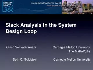
Slack Analysis in the System Design Loop Girish Venkataramani Carnegie Mellon University, The MathWorks Seth C. Goldstein Carnegie Mellon University
Typical System Design Flow Spec. Scalability Issues: Simulation takes minutes to hours Synthesis takes many hours System Partitioning Mapping + Allocation IR System Design Loop Code Emission Simulation RTL (*.v, *.vhd) Too slow! Physical Synthesis
Proposed Design Flow New Optimization Loop Traditional System Design Loop Spec. System Partitioning Update timing in IR Mapping + Allocation IR replace with Optimize Design Code Emission Simulation RTL (*.v, *.vhd) Physical Synthesis Timing Analysis
Key Contributions New Optimization Loop Traditional System Design Loop Spec. System Partitioning Update timing in IR Mapping + Allocation IR replace with Optimize Design Code Emission • Slack is a distributed representation of system timing • Linear-time update algorithm based on slack • > 100x reduction in total design time: • Optimization Loop runs in seconds/minutes while • System Design Loop runs in hours/days Simulation RTL (*.v, *.vhd) Physical Synthesis Timing Analysis
Outline • Motivation • Timing Metrics • Cycle time • Slack: An alternative view of cycle time • Slack Update Algorithm • Experimental Evaluation • Conclusions
Models a dynamic system Concurrent sub-systems PE, FSM, S/W, Memory Communication between sub-systems based on pre-defined protocols FIFOs, NoC, shared bus The Intermediate Representation (IR) … … Sub-System Sub-System Network … … Sub-System Sub-System Transaction-Level Modeling (TLM), [Cai, ISSS 03] Adopted by System-C, Bluespec, Balsa, Tangram
Model dynamic system interactions Events and transitions Event: An edge acquires a token Transition: Node consumes inputs and generates outputs Encode the communication protocols Marked Graphs token S1 S2 S3
Timing Analysis of IR • Time Separation between Event (TSEs) • TSE between consecutive firings of same event in steady state is the mean cycle time • Mean Cycle Time, CT • Computing CT is about O(|E|3) complexity [Dasdan 04]
Slack as a Timing Metric S1 S2 locally critical 2 5 S3 8 • Distributed representation of cycle time • Different type of TSE • Defined on each (input edge, node) pair • How early this input arrives Slack(S1, S3) = 3 Slack(S2, S3) = 0 Slack(S3, S1) = 0 Slack(S3, S2) = 0 • Zero-slack input is locally critical • Longest chain of zero-slack events yields the critical cycle or the Global Critical Path (GCP) • Cycle time = Latency of the GCP • Given slack values, computing cycle time has linear complexity *
Slack is an Annotation on the IR Slack Slack Slack Slack … … Sub-System Sub-System Network … … Sub-System Sub-System Helps in discovering hotspots and applying optimizations
Outline • Motivation • Timing Metrics • Slack Update Algorithm • Experimental Evaluation • Conclusions
Optimizations Change the IR New Optimization Loop Spec. System Partitioning Update timing in IR Mapping + Allocation IR + slack Optimize Design Code Emission Simulation RTL (*.v, *.vhd) Causes changes in component delays, in turn, changing in slack values Need to update slack on each change Physical Synthesis
Problem Description 2 5 8 • Given a graph model and its current slack values, compute new values of slack when latency of a node changes by a given Δ S1 S2 S3 6, Δ = -2
Insight behind Update Algorithm sfork • Slack is also latency difference of two branches of a re-convergent fork-join • If delay of node, sc, increases by Δ • Update slack in surrounding re-convergent fork-joins • Propagate change globally +Δ sc P2 P1 e2 e1 sjoin Assume δ(P1) > δ(P2), Di = δ(P1) - δ(P2) Slack(e1, sjoin) = 0 Slack(e2, sjoin) = Di Update (let Δ ≤ Di): Slack(e2, sjoin) = Di + Δ
If there is a path from change point to every input of sjoin, then no change in slack If not, then slack changes occur Insight behind Update Algorithm sfork +Δ +Δ sc e2 e1 sjoin Easy for acyclic graphs, but what about scc graphs?
Insight for Cyclic Graphs 2 5 8 2, Δ = -3 • Use token knowledge • Count tokens from change point to every input • If value is equal for all inputs, then no change in slack values S1 S2 # toks = 1 # toks = 2 S3 Change in slack exists
Insight for Cyclic Graphs 2 5 8 6, Δ = -2 • Use token knowledge • Count tokens from change point to every input • If value is equal for all inputs, then no change in slack values # toks = 0 # toks = 0 S1 S2 S3 No change in slack
Algorithm Summary • Initially, find # tokens between every pair of nodes in the graph • Problem formulated as a flow lattice • Invoked once, complexity is O(|M0| |V|) • After inducing every change in graph • Compute slack change at each node • Propagate new change to neighboring outputs • Overall complexity is O(|V|)
Outline • Motivation • Timing Metrics • Slack Update Algorithm • Experimental Evaluation • Conclusions
Experimental Setup • Slack Update loop incorporated into CASH compiler [ASPLOS 04, DAC 07] • Synthesizes asynchronous circuits from ANSI-C programs • Applied three different optimizations • SM: Slack Matching [ICCAD 06] • OC: Operation Chaining [ICCAD 07] • ASU: Heterogeneous Pipeline Synthesis [Async 08] • Benchmarks: Fifteen frequently executed kernels from Mediabench suite, [Lee 97] • All results are post-synthesis mapped to ST Micro 180nm library
Absolute Accuracy • After SM, compare computed values of slack against actual values of slack for adpcm_d • Close to 100 changes applied (algo invoked for each change) • 1.2x performance speedup • Update inaccuracy due to unknown latency values during circuit transformation
Design Loop Experiments Optimization Loop System Design Loop Run the same N optimizations in both loops and compare: 1. Overall Performance change 2. Overall design time Spec. System Partitioning Update timing in IR Mapping + Allocation IR Optimize Design Code Emission Simulation RTL (*.v, *.vhd) Physical Synthesis Timing Analysis
Design Loop Experiments • Three optimization sequences • SM-ASU: Slack matching followed by Heterogenous latch insertion • ASU-SM • SM-ASU-OC • Compare final circuit timing and loop traversal (design) times between the two methodologies
Design Loop Experiments SM-ASU ASU-SM • About ~500 circuit changes, on average • Design Loop time: 0.5 – 4 hours • Optimization loop: 10 - 100 seconds
Design Loop Experiments: SM-ASU-OC • About ~1000-3000 circuit changes, on average • Design Loop time: 1 – 10 hours • Optimization loop: 20 - 200 seconds 300x Speedup
Outline • Motivation • Timing Metrics • Slack Update Algorithm • Experimental Evaluation • Conclusions
Conclusions • Slack update algorithm to speed up design loop in TLM-based workflows • Use slack to track system-level timing changes • Orders of magnitude reduction in design time at negligible loss in accuracy • New optimizations loop enables scalability in iterative system design flows