Download
1 / 8
80 likes | 195 Views
4.7 mm. 4.3mm. R&D for single gap. Use the HARDROC ASICs , SiGe technology (well tested and available) HARDROC : 64-channel, 2-bin readout (3 comparators, 3 thresholds), Dynamic range : 10fC-10pC Use SDHCAL DAQ (available)

E N D
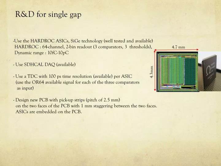
4.7 mm 4.3mm R&D for single gap • Use the HARDROC ASICs, SiGe technology (well tested and available) • HARDROC : 64-channel, 2-bin readout (3 comparators, 3 thresholds), • Dynamic range : 10fC-10pC • Use SDHCAL DAQ (available) • Use a TDC with 100 ps time resolution (available) per ASIC • (use the OR64 available signal for each of the three comparators • as input) • Design new PCB with pick-up strips (pitch of 2.5 mm) • on the two faces of the PCB with 1 mm staggering between the two faces. • ASICs are embedded on the PCB.
Charge DIF #1 Charge DIF #2 DAQ soft DAQ soft Time DIF #1 Time DIF #2 DAQ soft DAQ soft OR64 OR64 T = N0Tslow - N1Tfast
Charge DIF HR2 (top left strips) HR2 (top right strips) HR2 (bottom left strips) HR2 (bottom right strips) TDC DIF
Preliminary results (1) ASU SDCC DCC Q DIF HR2 PC RPi T DIF USB Trigger Pulse generator (HP33250) • Injection is made with a pulse generator on one strip (otherchannels are disabled) • Pulse generatoristriggeredby the DIF (synchronouswith the DIF clock) • Delay between pulse and trigger isadjustedinside the generator
Preliminary results (2) 30 mm from start of strip (run 13424) 6mm from start of strip (run 13411) • around 2,6 ns/m on the PCB even if obviously not linear Can certainly be refined but not too far from curently accepted values
R&D for multi gap and <100 ps time resolution • Use the 16-channel PETIROC ASICs (available) : • High bandwidthpreamp (GBWP> 10 GHz), <3 mW/ch, dual time and charge measurement up to 2500 pe, jitter< 10 psrms • Use a TDC with 25 ps time resolution (available) per ASIC • (use the ∪16 available signal) • Design new PCB with pick-up strips • ASICs and the LB are on the same PCB (on the edge) • the two strip’s ends are read out so one can have both • hit position and time resolution OMEGA group
24Ch 25ps TDC module 100M Ethernet Readout with TCP/IP support Cyclone-II FPGA EP2C35F484C6 Socket for TCXO (opt.) Tsinghua university Differential input connector
Strips are read out from both sides to get position and time measurement • The off-detector strips are on the edges (5-10 mm on each side?) and out of the detector • Strips are buried in an insulator layer. The PCB is to be inserted between two RPC. • ASICs and TDCs on one side. Limited zone is allowed. On-detector Strip Off-detector Strip