Download
1 / 11
120 likes | 414 Views
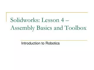
Solidworks Lesson 5 - Assembly Configurations and Motion . Introduction to Robotics. Solidworks. During the last lesson we learned how to construct assemblies using the basic mating constraints that are present in SolidWorks.

E N D
Solidworks Lesson 5 - Assembly Configurations and Motion Introduction to Robotics
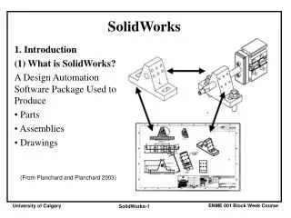
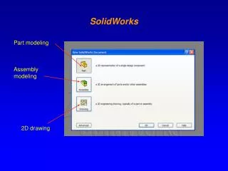
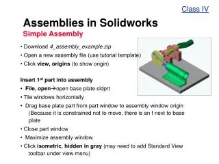
Solidworks • During the last lesson we learned how to construct assemblies using the basic mating constraints that are present in SolidWorks. • The first thing that we are going to do this lesson is look at how we can create alternate configurations for the assembly, in order to represent exploded or section views.
Solidworks Begin by opening the assembly that we created last lesson.
Configuration Manager Oftentimes, when we are creating assemblies we want to show an exploded view which illustrates to the reader how to assemble/disassemble the part. SolidWorks provides us an excellent tool in the Configuration Manager to allow us to construct exploded views of our part.
Configuration Manager Using the configuration manager we can create different “configurations” of our part which we can turn on and off on the fly. This way, we only have to create a view one time, then we can display it at any point with the click of a button.
Configuration Manager Click the THIRD TAB that is with the Feature and Property Manager. To create an EXPLODED view. RIGHT CLICK on DEFAULT. Choose NEW EXPLODED VIEW. Property Manager will then open.
Creating an Exploded View Click on one of the HEX Nuts. You will see it appear under settings. You will also see an axis. Click and Hold on any chosen direction to DRAG the part away from the main assembly. Click on the vertical arrow and drag the hex nut below. You will then see an “explode step”. Double click on this and change the distance to 0.05m. Click APPLY then DONE!
Creating an Exploded View Repeat procedure for second hex nut then repeat for each hex screw. The screw should be pulled UPWARD and the distance set to 0.07m. Repeat for other screw.
Creating an Exploded View Now click on the lower saddle and move it downward 0.025 m.
Creating an Exploded View Click OK in configuration manager or hit OK to exit sketch. You should see after exiting a NEW “Explview1” If you RIGHT CLICK on the original assembly, you can collapse the assembly. Likewise, if you RIGHT CLICK on the assembly again in configuration manager, you can EXPLODE the assembly.
Animating Configurations To animate the collapse/explode, right click on the configuration and choose ANIMATE EXPLODE or COLLAPSE. You can have it continue to explode and collapse if the RECIPROCATE button is pressed on the Animation controller.