Download

1 / 19
190 likes | 295 Views
HV-Splitter for RENO Project. S. Stepanyan, 김우영 경북대학교 Y.Kim Sejong University May-2008. PMT-base circuit. A-high Potential; back terminated for large signals by 50ohm and 4.7nF cap. to ground

E N D
HV-Splitterfor RENO Project S. Stepanyan, 김우영 경북대학교Y.Kim Sejong University May-2008.
PMT-base circuit • A-high Potential; back terminated for large signals by 50ohm and 4.7nF cap. to ground • K-photocathode should be kept at ground potential to avoid discharges which might be occur between K and outer envelope of the detector. • RG303C 50 ohm cable sealed in the PMT base with SHV connector. 0.1mA divider
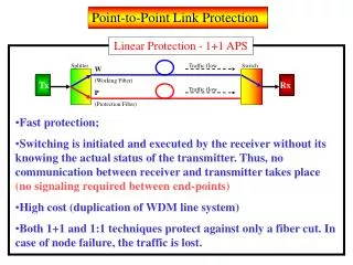
HV Splitter Circuit • HV PS outputs should be floating, such that crate ground is independent of the return for the HV channels. • 100ns single cable for readout and supply of HV which minimizes the ground loops noise. • Having termination at both PMT base and the HV splitter (100 ns cable) reduces the reflections to 1%.
HV Splitter Goals • Expected PMT signals ~2mV which passing first through HV-splitter • Decouple the signals coming out PMT s from the HV supplies. • Terminate the PMT cable transmission line to minimize pulse reflections, • Distribute HV among several PMT s per HV channel. • Provide filtering of the HV to reduce noise comes from HV supplies .
The HV(High Voltage) system configuration from microchips of DC to DC HV generators of EMCO or CAEN • Model A864 provides a programmable and monitorable output voltage ranging from 0 to 2kV when supplied 12v input voltage, size 25mmmx100mmx13mm; one ch. manufacturer CAEN • A3006 6channel 4-16V/6A/90W(per ch.) LV PS from CAEN • A3802 128ch DAC(12bit resolution) +4V/10mA DAC(digital analog convertor)
EMCO+ CAEN with 4 additional wires to PMT base(2 input and 2 from DAC for programming control)length of wires should be same for all PMT dividers • . A) model CA20P-5 . DC to DC HV generator manufacturer of EMCO • B) model CM1One ch.CA series Chassis mount kit manufacturer of EMCO. • C) A3009 12ch 2-8V/9A/45W(per ch) manufacturer CAEN • D) A3802 128ch DAC(12bit resolution) +4V/10mA DAC manufacturer CAEN.
AS a Day Bay proposal. • . By using manufacturer Analog, Inc. Microcontroller ADuC845/ADuC847/ADuC848 . • DC to DC HV generator manufacturer of EMCO. Also we should think about LV PS and should develop software of the microcontroller
End • Thank you for Attention