Download
1 / 10
100 likes | 206 Views
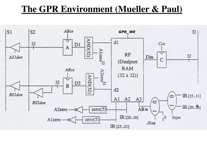
The GPR Environment (Mueller & Paul). GPR_WE. The GPR Environment (Cont.). GPR_WE. Drivers to enable the writing of a value to the bus. The GPR Environment (Cont.). GPR_WE.

E N D
The GPR Environment (Cont.) GPR_WE Drivers to enable the writing of a value to the bus.
The GPR Environment (Cont.) GPR_WE A1, A2 are the registers to be read from and A3 is the register to be written to. Their values are trivial-derived from the IR register.
The GPR Environment (Cont.) GPR_WE R0 always equals zero: Zero Testers check if A1 or A2 equal zero.If so, the A1Zero / A2Zero signals equal zero.
The GPR Environment (Cont.) GPR_WE a read from R0 results with a zero value written to the appropriate register (A or B).
The GPR Environment (Cont.) GPR_WE A3 can be either IR[15:11], IR[20:16] or 11111. Its value is according to the instruction’s type (I-Type or R-Type). The I-Type Control signal “decides” what type of instruction we deal with.
The GPR Environment (Cont.) GPR_WE When dealing with the jalr instruction, we have to write to R31 and at that case, the Jlink signal gets the value of 1.
The GPR Environment (Cont.) GPR_WE Remember: The GPR Env. is a dual-port RAM that supports either two Read operations or one write operation at a certain time.
The PC Environment The PC Env. is implemented as follows: This constant is used in the Decode stage when advancing the PC to be PC+1 When the computer is turned on, the PUP signal=1 , the MUX and the Control signal PCsce get a “1” value and as a result the PC is initialized to the address. The DINT bus feeds the new PC.
The ALU Environment ALU • The ALU supports: • 2’s complement integer addition operations • 2’s complement integer subtraction operations • Comparison operations • Bitwise logical operations • A comparison is implemented by subtraction and • examination of a sign-bit and a zero-tester