Download

1 / 91
1.04k likes | 1.67k Views
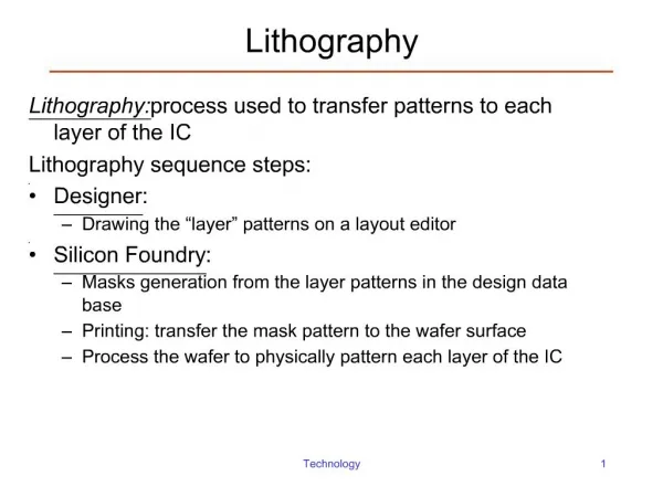
Microelectronics Processing Lithography. Photolithography. Photolithography is the sequence of activities needed for transfer a pre-designed pattern to the surface of a semiconductor wafer . The pattern can be registered on a mask, or supplied directly from a computer to a scanning

E N D
Photolithography Photolithography is the sequence of activities needed for transfer a pre-designed pattern to the surface of a semiconductor wafer. The pattern can be registered on a mask, or supplied directly from a computer to a scanning radiation source. Photoresist is a photo-sensitive resistant coating used to register an image on the desired surface
Lithography Wafer printing process: • Light sources • Exposure techniques • Photoresist • Mask engineering Novel process • E-beam lithography
i-line (365 nm) g-line (435 nm) h-line (405 nm) Light Sources: The Hg Lamp
Optics: Basics of Diffraction Assume a circular aperture of radius r0 We define a parameter u as u=(2/)r0sin The far field radiation pattern of the aperture I(u) I(0) (J1(u)/u)2 J1(u) is the 1st Bessel Function
Optics: Basics of Projection Systems Note that the aperture (or lens) diameter determines the value of
Rayleigh’s definition of resolution Resolved images Unresolved images Resolution
Depth of focus In-focus Out-of-focus Source: http://emalwww.engin.umich.edu/emal/courses/SEM_lectureCW/SEM_DepthofFocus.html
Example of Depth of Field problem Need a DOF larger than
Modulation Transfer Function MTF is a function of feature size! MTF= (IMAX-IMIN)/(IMAX+IMIN)
Contact and Proximity Printing(Fresnel diffraction) =365 nm
Critical Dimension Control (Math work on the board)
Photoresist (3) Novolac
PAC Changed due to illumination
(h) soluble on basic solution H2O
Basic Properties of Resists Contrast:
Critical MTF (CMTF) CMTF is the minimal MTF value of the optical system that results in a fully resolved pattern in the photoresist
Spin-on photoresist t = thickness K = constant S= fraction of solids υ= viscosity ω= angular velocity R = radius Thickness of PR t=KS(/ω2R2)1/3
Constructive interference Destructive interference Other issues in Photoresist Exposure
Mask Engineering: OPC With OPC Desired Mask Printed
Optical lithography - Steps required for a pattern transfer (7) Photoresist removal
Spin coat Pre-bake Substrate cleaning Develop Post exposure treatment Expose Plasma de-scum Etch Post bake Strip *Steps in dashed (pink) lines are not always used Flow chart of a typical resist process HMDS 900C 1400C