Download

1 / 20
490 likes | 1.66k Views
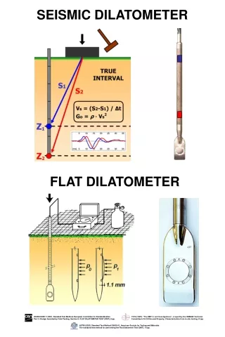
An Introduction to Dilatometer Testing. Paul J. Cosentino, Ph.D., P.E. Professor Civil Engineering Department. The Marchetti Dilatometer. The Dilatometer (DMT) is pushed into the soil. The blade is tapered on both sides so it goes straight down. What is the Dilatometer (DMT)?.

E N D
An Introduction to Dilatometer Testing Paul J. Cosentino, Ph.D., P.E. Professor Civil Engineering Department
The Marchetti Dilatometer The Dilatometer (DMT) is pushed into the soil. The blade is tapered on both sides so it goes straight down
What is the Dilatometer (DMT)? • A fast in-situ test designed to evaluate lateral soil properties • Push DMT to desired depth with Cone Rods • Typically one meter or five foot intervals used • Use Compressed Nitrogen to apply pressures • Measure “lift-off” pressure • Correlated to Ko [“A”] • Measure pressure at 1.1 mm membrane expansion [“B”] • Unload quickly and measure hydrostatic pressure [“C”] • Caution when checking u in clays since Du could influence results • Results in sands were reasonable
The Cone Truck Cone Rods are Pushed through this portion of the rig.
Control Unit with Calibration Tube Calibration tube
Basic Testing Process • Perform initial calibrations for DA and DB and record Zm • DA is the pressure inherent to the system required to cause membrane lift off (i.e., w/o soil) • DBis the pressure inherent to the system at 1.1 mm membrane movement (i.e., w/o soil) • Zm gage reading when vented to atmosphere • Push DMT to desired depth • Typically one meter or five foot intervals used • Use Compressed Nitrogen to apply pressures • Measure “lift-off” pressure [“A”] • Measure pressure at 1.1 mm membrane expansion [“B”] • Unload quickly and measure hydrostatic pressure [“C”] • Caution when checking u in clays since Du could influence results
DMT Control Unit Pressure Source Ground Flow Vents
CPT Truck Hydraulic Controls Operator sets DMT test depth
Loading at 1.1 mm to determine Maximum Pressure “B”parameter
Basic Engineering Parameters Initial Pressure po = 1.05 (A-Zm+A)-0.05(B- Zm -B) Limit Pressure pl = B-Zm-B Material Index = ID = (pl-po)/(po-uo) Horizontal Stress Index = KD =(po-uo)/’vo Dilatometer Modulus = ED = 34.7 (pl-po)
Additional Engineering Parameters At-Rest Earth Pressure = Ko =(KD/1.5)0.47- 0.6 for ID<1.2 Young’s Modulus
Questions • Given DA = 0.15 DB = 0.25 Zm = 1.0 • At 1.5 m A = 3.95 B = 27.5 • At 2.5 m A = 1.61 B = 2.37 C =0.61 • All pressures are in Bars • Find the following for both depths* • The Initial Pressure • The Limit Pressure • The Dilatometer Modulus • Young’s Modulus* (Only at 2.5 m)