Download
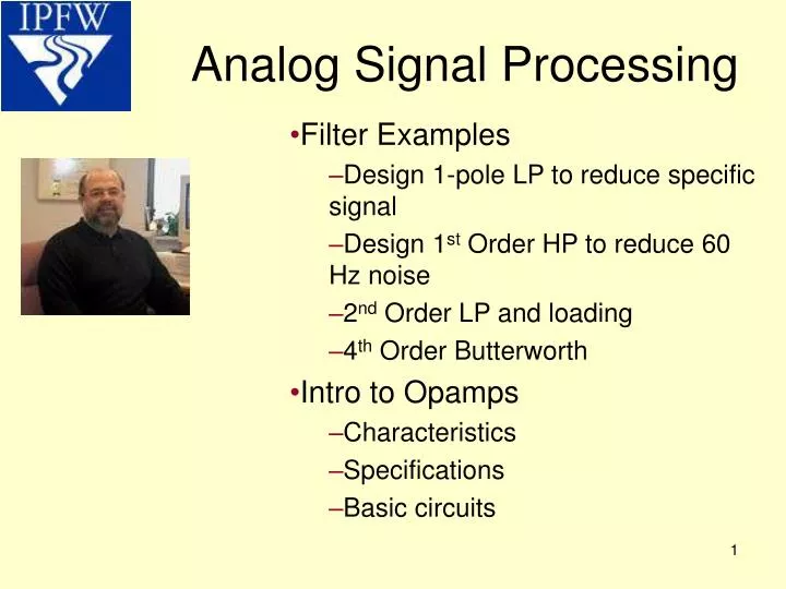
1 / 21
340 likes | 740 Views
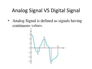
Analog Signal Processing. Filter Examples Design 1-pole LP to reduce specific signal Design 1 st Order HP to reduce 60 Hz noise 2 nd Order LP and loading 4 th Order Butterworth Intro to Opamps Characteristics Specifications Basic circuits. Derivation: Review. Final Result remember

E N D
Analog Signal Processing Filter Examples Design 1-pole LP to reduce specific signal Design 1st Order HP to reduce 60 Hz noise 2nd Order LP and loading 4th Order Butterworth Intro to Opamps Characteristics Specifications Basic circuits
Derivation: Review Final Result remember square root of sum of squares Remember that the cutoff frequency of a 1st order RC filter is:
Design a 1-pole LPF to reduce the undesired 50KHz signal by 32 dB in voltage. Also, find the cutoff frequency of the filter And solving for Vout/Vin yields .025119 Remember that: Now, solving the top equation for fc you get fc = 1256 Hz
Design a 1-pole LPF to reduce the undesired 50KHz signal by 32 dB in voltage. Also, find the cutoff frequency of the filter Since Choose a convenient value for the capacitance, say .01 uF, then solve for the required resistance. Thus, R = 12.67 kΩ
Design a 1st order HP filter to reduce 60 Hz noise by 20 dB in Power
Design a 1st order HP filter to reduce 60 Hz noise by 20 dB in Power fc = 180 Hz If you choose C = 1 uF then R=884 Ω
2nd Order LP Filter Figure 1: For a 1st order LP filter fc = 1256 Hz Figure 2: For a 1st order LP filter fc = 1256 Hz Ideal
Transfer Functions To calculate the transfer function you need to find Vout/Vin which is quite difficult with complex numbers. This transfer function is just the transfer function of one filter squared. At f = 1256 this equation equals ½. 20Log10(.5)=-6dB
Passive Butterworth filtershttp://members.aol.com/maxfro/private/butter.html
OpAmps http://socrates.berkeley.edu/~phylabs/bsc/PDFFiles/bsc7.pdf
http://www.national.com/pf/LM/LM741.html Op Amp specifications
Basic Op Amp Circuits:Inverting op amp http://www.es.oersted.dtu.dk/~c49102/Circuit03.html
Basic Opamp Circuits:Voltage Follower (non-inverting) http://www.es.oersted.dtu.dk/~c49102/javalab.html#examples
More opamp circuits VLoad=-5V1-2V2-V3 VLoad=(1+Rf/R1)*Vin VLoad=(R2/R1)*(V2-V1)
Summary • Filter Examples • Design 1-pole LP to reduce specific signal • Design 1st Order HP to reduce 60 Hz noise • 2nd Order LP and loading • 4th Order Butterworth • Intro to Opamps • Characteristics • Specifications • Basic circuits