Download
1 / 25
250 likes | 369 Views
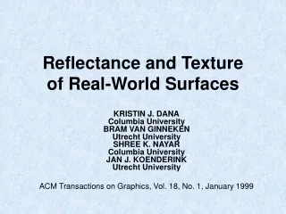
Reflectance and Texture of Real-World Surfaces. KRISTIN J. DANA Columbia University BRAM VAN GINNEKEN Utrecht University SHREE K. NAYAR Columbia University JAN J. KOENDERINK Utrecht University ACM Transactions on Graphics, Vol. 18, No. 1, January 1999. Overview. Introduce BRDF and BTF

E N D
Reflectance and Texture of Real-World Surfaces KRISTIN J. DANAColumbia UniversityBRAM VAN GINNEKENUtrecht UniversitySHREE K. NAYARColumbia UniversityJAN J. KOENDERINKUtrecht University ACM Transactions on Graphics, Vol. 18, No. 1, January 1999
Overview • Introduce BRDF and BTF • BTF Texture Gathering Technique • CUReT Database • BTF Applications • Future Work • Pretty Pictures
Bidirectional Reflectance Distribution Function (BRDF) • Nicodemus [1970] and Nicodemus et al. [1977] • Coarse scale level • local surface variations are subpixel • local intensity is uniform • Bidirectional: • Camera Angle • Light Angle • “Objects look differently when viewed from different angles, and when illuminated from different directions”
Bidirectional Texture Function (BTF) • Fine scale level • Surface variations give rise to local intensity variations • Bidirectional: • Camera Angle • Light Angle • “Objects look differently when viewed from different angles, and when illuminated from different directions”
Why do we need BTFs? • Traditional 2-D texture synthesis and texture-mapping do not take into account the change in texture appearance as the viewing and illumination directions change • A single digital image of a rough surface is mapped onto a 3-D object and the appearance of roughness is usually lost or distorted • Bump-mapping [Blinn 1977, 1978] preserves some of the appearance of roughness • knowledge of the surface shape is required • shadows cast from the local surface relief are not rendered • ray tracing can be used • exact geometry of the surface must be known • high computational cost • solid texturing: combine a volumetric texture synthesis with volume rendering techniques • computationally intensive • applicable for a limited variety of textures. • BTF database • “potential exists for 3-D texturing algorithms using images, without the need for a volumetric texture model or surface synthesis procedure”
BTF: Where do we start? • Already BRDF databases • Employ new techniques to create BTF database • Pull Together: • Robot • Lamp • PC • Photometer • Video camera
Texture Gathering Technique • Fixed light source • Halogen bulb with a Fresnel lens (single- beam focusing) • Camera moves through 7 positions • 22.5°, 45°, 67.5°, 90°, 112.5°, 135°, 157.5° from light source • Texture sample moves through multiple orientations • Robot arm orients sample normal along vertices of quarter-sphere facing the light source
Texture Gathering Technique Quarter-Sphere Orientations: Camera Positions • At each camera position, texture is captured with its normal along quarter-sphere vertices • Not all vertices captured at each position • At position 7, only a few normals are actually visible to the camera
Texture Gathering Technique Quarter-Sphere Orientations: Illumination Directions • Sample lies in xs–ys plane with its global normal pointing in the direction of zs • Each circular marker represents a distinct illumination direction • For each of these illumination directions, the sample is imaged from seven viewing directions
Texture Gathering Technique Special Case: Anisotropic Textures • Textures that have grids or grains • Measurements are repeated rotating sample about zs by either 45° or 90° depending on the structure of the anisotropy • Examples: • Linen (square grid) rotated 45° • Corduroy (vertical lines) rotated 90 °
Texture Gathering Technique Control Considerations • Relate radiance to pixel values • Use Kodak standard card image for every sample measured. • Letting r denote the total radiance and p denote the average pixel value, a linear relationship was found • Data with significant pixel underflow (pixel values near 0) or overflow (pixel values near 255) were not used.
End Product • 205 images for each sample • 640 x 480 pixels • 24 bits per pixel (8 bits per RGB channel). • Database total: over 14,000 images (61 samples, 205 measurements per sample, plus 205 additional measurements for anisotropic samples) • CUReT Database: www.cs.columbia.edu/CAVE/curet/
BTF Applications • Top row • Two images of “plaster_b” with different illumination and viewing directions • Bottom row • Spatial spectrum of “plaster_b” with zero frequency at the center and brighter regions corresponding to higher magnitudes • Notice orientation change due to change of illumination direction causing change in shadow direction. • Computer vision: • Texture recognition algorithms often based on spectral content of image textures • BTF should be considered for recognition of real-world surfaces Sample 11: “plaster_b”
BTF Applications • BTF texture gathering technique allows easy gathering of BRDF data • Pros: • Simple system • Simultaneously gather BRDF and BTF measurements • Cons: • Not as accurate as traditional BRDF measurement systems
Future Work Synthesizing Bidirectional Texture Functions for Real-World Surfaces Xinguo Liu, Yizhou Yu,Heung-Yeung Shum • 3 Step approach to synthetically generate BTFs • Recovers approximate 3D geometry of surface details using a shape-from-shading approach • Generates a novel version of the geometric details with the same statistical properties as the sample surface • Uses an “appearance preserving procedure” to synthesize novel images under various viewing/lighting settings, defining a novel BTF
Show me some BTF pictures!!! • 13 images per sample used from database collection of 205 • 1 image of frontal view • 12 oblique views • Use averaging of three pixels at the section borders to reduce the appearance of seams
Pretty Pictures Sample 11 (plaster) Traditional 2-D texture-mapping BTF 3-D texture-mapping
Pretty Pictures Sample 8 (pebbles) Traditional 2-D texture-mapping BTF 3-D texture-mapping
Pretty Pictures Sample 45 (concrete) Traditional 2-D texture-mapping BTF 3-D texture-mapping
Pretty Pictures Sample 28 (crumpled paper) Traditional 2-D texture-mapping BTF 3-D texture-mapping
Pretty Pictures Sample 19 (plush rug) Traditional 2-D texture-mapping BTF 3-D texture-mapping
Pretty Pictures Sample 56 (wood) (anisotropic) Traditional 2-D texture-mapping BTF 3-D texture-mapping

![Texture Synthesis on [Arbitrary Manifold] Surfaces](https://cdn2.slideserve.com/4198281/texture-synthesis-on-arbitrary-manifold-surfaces-dt.jpg)