Download
1 / 1
10 likes | 110 Views
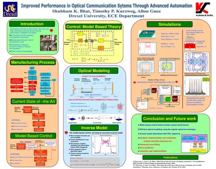
Introduction. Simulations. Automation is the key to high volume, low cost, and high consistency manufacturing ensuring performance, reliability, and quality . Array of 8 fibers to the wave guide outputs of a star coupler. Aperture = 20um x 20um Fiber Core = 4 um Prop. Distance = 10 um.

E N D
Introduction Simulations Automation is the key to high volume, low cost, and high consistency manufacturing ensuringperformance, reliability, and quality. Array of 8 fibers to the wave guide outputs of a star coupler Aperture = 20um x 20um Fiber Core = 4 um Prop. Distance = 10 um • No standard for OE packaging and assembly automation. • Misalignment between optical and geometric axes • Packaging is critical to success or failure of optical microsystems • 60-80 % cost is in packaging Fiber Array Edge Emitting Laser Coupled To a Fiber R(s) Pr(s) Pd(s) Kp E(s) + + Wavelength =1550nm + - Received Power Desired Power Distance = 10um No. of. Peaks = 10 Star Coupler Input Tilt = 2o Kp NEAR FIELD COUPLING Power measured using a fiber detector of 4um core diameter Current State-of-the-Art Alignment If = P, Start Manufacturing Process Input Power Measurement & Loading Step 1 Camera With Microscopic Lenses Initial Throughput And Coarse Alignment Optical Modeling Frame Grabber Step 2 Time Pulsed or Positive-Displacement Adhesive Dispenser DAC Motion Controller Control And Optimization Difference between conventional and model-based technique of fiber positioning Step 3 Actuator that holds Receiving Device Feed Forward Set Point (Power) Alignment with Feed Forward VALIDITY OF SCALAR MODELS Position @ Pmax= 12.6 um Adhesive Application ( Epoxy ) Bonding Step 4 Rayleigh-Sommerfeld & Fresnel-Kirchoff Fresnel (Near Field) Fraunhofer (Far field) Full Wave Solutions First Light Detection Step 5 Post-Binding Testing INCREASED SYSTEM PERFORMANCE OVER 18% UV Curing Photo Detector Unloading Step 6 Optical Power Meter End 20 1.5 Fiber Position (12.6 um) 18 1.3 Inverse Model 16 1.1 Received Power + 14 Microsystems 0.9 Derivative (1.41 ) 12 + 0.7 Scalar Approximations 50mm 200mm 850nm 966um 4.66mm Comparing the power in both the cases, we get an increase in performance of 33% Nominal Model Desired Power Proportional Gain + Current State-of –the-Art SCALAR DIFFRACTION-RAYLEIGH SOMMERFELD FORMULATION: + K (1.41) - Motor Dynamics Plant Model 1.5 x • Diffractive component >>λ • Distance to observation plane >>λ y 1 K r 0.5 Proportional Gain Assembly Alignment Task Parameters Visual Inspect and Manual Alignment ApproximateSet Point=Xo z Time Taken = 7 seconds 0 U2(x,y) U1(,) Initialization Loop Move to set point (Xo) Measure Power (Po) Conclusion and Future work • LIMITATIONS: • Multi-modal Functions • Multi-Axes convergence • Slow, expensive Off the shelf Motion Control (PID) (Servo Loop) • Model based control leads to better system performance • Efficient optical modeling using the angular spectrum technique • Inverse model determined with PWL segments Inverse Model SpatialDomain SpatialDomain FourierDomain Stop motion Fix Alignment For model based control, we need an accurate inverse model Model-Based Control • Most transfer functions are non-invertible • Power distribution is non-monotonic • Decompose complex waveform into Piece-Wise Linear (PWL) Segments • Each segment valid in specified region • Find an inverse model for each segment • Hardware implementation and verification • - Kulicke and Soffa Industries Inc. • Advanced curve-fitting • Error prediction • Learning Loop implementation Correction to Model Parameter Learning Algorithm Model Parameter Adjustment FEED - FORWARD Set Point=Xo Visual Inspect and Manual Alignment Assembly Alignment TaskParameters Optical Power Propagation Model {Xk}, {Pk} Initialization Loop Move to set point (Xo) Measure Power (Po) • ADVANTAGES: • Support for Multi-modal Functions • Technique is fast • Cost-efficient Publications Off the shelf Motion Control (PID) (Servo Loop) T.P.Kurzweg, A. Guez, S. K. Bhat, “Model Based Opto-Electronic Packaging Automation,” to be published in IEEE Journal of Selected Topics in Quantum Electronics, 2004. T.P. Kurzweg, A. Guez, S. K. Bhat, “Knowledge Based Design of Optoelectronic Packaging and Assembly Automation,” Photonics East Conference, Providence, RI., October 29-31, 2003. Stop motion Fix Alignment Improved Performance in Optical Communication Sytems Through Advanced Automation Shubham K. Bhat, Timothy P. Kurzweg, Allon Guez Drexel University, ECE Department Control: Model Based Theory