Download
1 / 20
200 likes | 209 Views
Meeting Minutes – 1/7/15. LF Solenoids: SOW has been split into SOW and Spec by Dave IAW PPM request. Will get out to bid by 1/9/14 if possible. HF (Matching) Solenoids Drawings complete and checked. Jorg and Dmitry to confirm design.

E N D
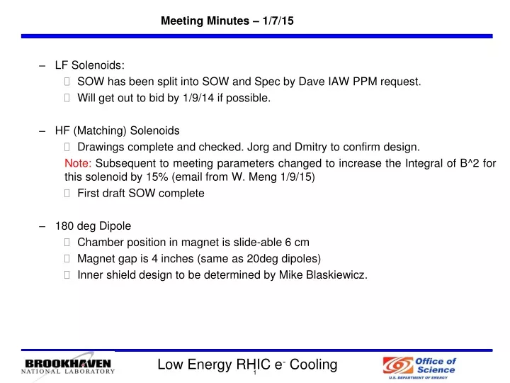
Meeting Minutes – 1/7/15 • LF Solenoids: • SOW has been split into SOW and Spec by Dave IAW PPM request. • Will get out to bid by 1/9/14 if possible. • HF (Matching) Solenoids • Drawings complete and checked. Jorg and Dmitry to confirm design. Note: Subsequent to meeting parameters changed to increase the Integral of B^2 for this solenoid by 15% (email from W. Meng 1/9/15) • First draft SOW complete • 180 deg Dipole • Chamber position in magnet is slide-able 6 cm • Magnet gap is 4 inches (same as 20deg dipoles) • Inner shield design to be determined by Mike Blaskiewicz.
Meeting Minutes – 1/7/15 • Beam Line • Vacuum valves 2.5” RF shielded in transport line. • Magnetic Shielding • 2.5 milligauss shielding of beam line required (AF). • Per Alexei the shielding of the instrumentation (esp., PM’s and slits) will be difficult. These devices should be kept as near to LF solenoids as possible. • Instrumentation: • BPM’s - small button standard design from MPF (or smaller). • Chuyu Liu to do simulations for emittance and energy slits and profile monitor to finalize design. • Instrumentation is on the critical path for installation of the Cooling Section in 2015.
LEReC-I (1.6-2MeV): Gun to dump SRF gun used as a gun 64 m IP2 Beam dump e- e- e- 704 MHz SRF gun 180 deg. bending magnet 5-cell 704 MHz SRF cavity 9MHz 704 MHz warm cavity 2.1 GHz warm cavity
64 m IP2 LEReC-I (1.6-2MeV): Gun to dump SRF gun used as a booster cavity Beam dump e- e- e- 704 MHz SRF gunconverted to booster cavity 180 deg. bending magnet DC gun 5-cell 704 MHz SRF cavity 9MHz 704 MHz warm cavity 2.1 GHz warm cavity
Cooling Sections 2 (matching) solenoids & PS. 2 high field H & V correctors – seperate assemblies(& PS) New: Cooling Sections
Compensating Solenoids In PPM (G. Woods) Revised SOW with Specification D. Passarello (PPM)
Matching Solenoids Matching Solenoid w/corrector • 2 required in cooling section w/o bucking coil • Corrector 100 Gcm, will be separate • Drawings Checked • Draft SOW for review.
180o Dipole Magnet Range of motion for magnet core?
Vacuum Hardware Large open 180o vacuum chamber: are there beam impedance concerns? Should the electron beam path be shielded? Similar issue for 20o chamber? Shield Vacuum Chamber. Design and order beamline RF shielded bellows. Order RF shielded valves.
Beam Dump Line to Vacuum Valve: (4) 20o dipoles 10 cm aperture
Scope: Cooling Sections Weak Quadurpole for energy spread meas. Em-Slit Alignment Laser Out to Extraction YAG YAG Blue Ring Au Ion Beam 180 Deg Dipole Au Ion Beam Yellow Ring Alignment Laser BPMs (16) In from Merger Energy Slits YAG Em-Slit YAG Recombination Monitors (8) Cooling Sections BPM = 16 YAG = 4 Emittance slits = 2 Energy Slits = 2 Recombination Mon = 8 Alignment Laser = 2
Scope: Extraction Defocusing Quadrupole YAG DCCT Faraday Cup (Beam Dump) BPM BLM Cage for loss distribution measurement Blue Ring Au Ion Beam From Cooling Sections Extraction BPM = 1 YAG = 1 DCCT = 1 Faraday Cup = 1
Procurement & Repurpose: High Priority Items Cooling Sections elements installed in 2015 shutdown (July ‘15 – Jan ‘16)
BPMs in Cooling Section (14 Locations) Signal Simulations: Simulations were made with the short electron bunches and long ion bunches to determine expected signal amplitudes on the buttons. Shared Pick-Ups: One dual plan station at each solenoid is shared by two electronics boards, one measuring ions and one measuring electrons. BNL Zync Electronics Design: Ion Beam: 16mVpk-pk Electron Beam: 450mVpk-pk • VME Form Factor • Use RHIC Controls Infrastructure • Configurable Front End RF Section • 39 MHz for Ions • 700 MHz for electrons • 4 x 400MSPS A/D Converters • 2 Planes of Measurement / Board • Integrated Front End Computer • FEC & FPGA on Single Chip (Zynq) • Ethernet Connectivity (x2) • Controls Network • High Speed Interface for Feedback • Test results below at the ATF with 9.3mm buttons showed better than 100um accuracy and 10um precision. γ= 4.1 Ions/bunch = 7.5E8 Charge/bunch = 9.48E-9 C RMS length = 3.2 m γ= 4.1 Charge/bunch = 100 pC RMS length = 100 ps RMS length = 30 mm Simulations: Courtesy of Peter Thieberger New Pickup Design: • Large Dia. BPM Housings • 28mm buttons • N-Type feedthrough • MPF Q7031-1
Profile Monitors – New designs for Cooling Section Low Power profile measurement • 4 or 6 stations • Two Position plunger (similar to ERL Design) • 100um thick YAG crystal • Impedance matching cage • Large cube for 5” beam pipe • Same optics as ERL design Photo courtesy of Radiabeam High Power profile measurement • 2 stations • Compact offset cam design • 9 μm carbon fiber passes beam only once @ 20 m/s • accelerate/coast/decelerate in two rotations • PMT detects X‐rays generated by the scattered electrons Photo courtesy of B. Dunham, Cornell
Emittance Slit Measurement • Low Power Operations Only • New Dual axis design for Horizontal & Vertical measurements. • Positioned 0.16 – 1 m upstream of profile monitor - Final spacing TBD… • Tungsten Slit mask, optimized for beam parameters - Mask 1.5mm thick… # slits & TBD… Dual Station Actuator retrofitted for new dual axis mask. Intensity Distribution at mask Image on profile monitor after drift distance ANALYSIS: An algorithm was developed for analyzing the image from a multi-slit mask for emittance measurement. Future plans are to automate the image analysis for on-line processing and data logging.
Energy Spread Measurements – 2 Locations Image of YAG as projected onto CCD Before Cooling Sections • σδ = 750μm • Resolution = σδ / PitchYAG • 750μm / 29μm/px = 25 px 4% Resolution Between Cooling Sections • σδ = 350μm • Resolution = σδ / PitchYAG • 350μm / 29μm/px = 25 px 8.3% Resolution • 2MP CCD: 1292h X 964v px • PitchYAG = proj-HCCD/pxv = 29μm/px σδ = ηδ = 1.5m(5x10⁻⁴) = 750μm σδ = 2Rδ = 2(0.35m)(5x10⁻⁴) = 350μm • Max. Energy Spread: Δp/p = <5e-4 • Beam Size (d): 1mm (dia.) • Double Slit before dipole & drift to YAG • May use Quadto increase resolution between cooling sections • Considering alternatives: • Dedicated energy spectrometer beam line • Cornell’s method of using deflecting cavity
Recombination Monitor: Ion Collection E-Ion RECOMBINATION: • Au+79 Au+78, Expected rate ~5e6 per second • Creates ions of wrong charge • Generates X-rays in cooling section • loss rate ≈ alignment Recombination detector concept showing two ionization detectors mounted in retractable roman pot systems. Courtesy of Peter Thieberger ION (wrong charge) COLLECTION: • Lost at predictable location (collimators)? • Detector: PMT + Counter • ! Lattice simulation predicts lattice aperture acceptance of Au+78 ions ! => Work underway to develop a lattice with dispersive section.
Recombination Monitor: Radiative Detector RADIATIVE RECOMBINATION DETECTION: • Recombination radiation • 10-80keV x rays emitted a shallow forward angle • Scintillators located at in COOLING SECTION • Detector • Scintillator + PMT + Counter • => loss rate ≈ alignment Doppler shifted gold capture K - X - rays for γ = 4.1 PMT detector Air-side Scintillator-Ring clamps around pipe Light guide Au+79+78 Event Doppler shifted Shallow forward angle X-ray Emission Courtesy of Peter Thieberger Expanded section of beam pipe