Download
1 / 14
220 likes | 587 Views
Power FET structure (DMOS and VMOS). Abstract.

E N D
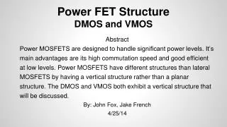
Power FET structure (DMOS and VMOS) Abstract Power MOSFETS are designed to handle significant power levels. It's main advantage are its high commutation speed and good efficient at low levels. Power MOSFETS have different structures than lateral MOSFETS by having a vertical structure rather than a planar structure. The DMOS and VMOS both exhibit a vertical structure that will be discussed. By Jared Hansen, Tyler Roschen 5/3/13
DMOS DMOS Structure VMOS VMOS Structure Outline
DMOS - Double-Diffused MOS Used in switching applications with high-voltage and high-frequency behavior DMOS Typically used in: • Automobile Control Electronics • Inkjet Printheads • Power Supplies
DMOS Structure • The DMOS device uses a double diffusion process • The p-substrate region and the n+ source contact are diffused through a common window defined by the edge of the gate • The p-substrate region is diffused deeper than the n+ source • The surface channel length is defined as the lateral diffusion distance between the p-substrate and the n+ source
DMOS Structure • Electrons enter the source terminal and flow laterally through the inversion layer under the gate to the n-drift region. • The electrons then flow vertically through the n-drift region to the drain terminal. • The convention current direction is from the drain to the source. Semiconductor Physics and Devices textbook by Donald A. Neamen
DMOS Structure • Most important characteristics are the breakdown voltage and on-resistance. • DMOS is similar to a BJT, due to the high-voltage and high-frequency characteristics • A lightly doped drift region between the drain contact and the channel region helps to ensure a very high breakdown voltage • The n-drift region must be moderately doped so that the drain breakdown voltage is sufficiently large • The thickness of the n-drift region should be as thin as possible to minimize drain resistance.
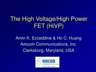
VMOS - Vertical Metal Oxide Silicon • Gets its name from the V-shaped gate region. VMOS http://sub.allaboutcircuits.com/images/03306.png
They have been established as a useful power MOSFET • VMOS FETs are used for a variety of applications where medium powers are required from power supply switching applications to medium power RF amplifiers. VMOS
VMOS Structure http://www.radio-electronics.com/info/data/semicond/fet-field-effect-transistor/vmos-structure.gif
The biggest feature in the structure of the VMOS is the Shaped groove. • It can be seen that the source is at the top of the device while the drain is at the bottom • So current flows vertically in the device instead of horizontally as in Standard FETS. VMOS Structure
V shaped gate increases the cross-sectional area of the source-drain path. This reduces the ON resistance of the device allowing it to handle much higher powers • The gate consists of a metallised area over the V groove and this controls the current flow in the P region. • The main drawback to the VMOS FET is that the structure is more complicated than the traditional FET and this makes it slightly more expensive VMOS Structure
Power MOSFETS differ from lateral MOSFETS with the vertical structure of the DMOS and the VMOS. These are used in a variety of applications that desire high switching speeds and a variety of voltage levels. The doping and channel lengths contribute to the characteristics of each of these MOSFETS. Summary
"VMOS Field Effect Transistor." :: Radio-Electronics.Com. N.p., n.d. Web. 30 Apr. 2013 "Insulated-gate Field-effect Transistors (MOSFET)." All About Circuits Forum RSS. N.p., n.d. Web. 30 Apr. 2013. "DMOS transistors in a BICMOS-technology". Alexandria.tue.nl. N.p., n.d. Web. 30 Apr. 2013 "A Look at DMOS Transistors". ChipWorks Inside Technology. N.p., n.d. Web. 30 Apr. 2013 Neamen, Donald. 2012. Semiconductor Physics and Devices. New York: McGraw-Hill References
Power MOSFETS have a vertical structure versus the usual planar structure. • DMOS uses a double diffusion process • Most important characteristics are the breakdown voltage and the on-resistance. • V shaped gate increases the cross-sectional area of the source-drain path. • The main advantages are the high commutation speed and its good effiency at low voltages. Key Points