Download
1 / 47
570 likes | 809 Views
Control of Fuel Cell Power Systems. Work funded by U.S. Army Center of Excellence for Automotive Research (ARC) and NSF-CMS 0201332 and CMS-0219623. Anna Stefanopoulou Department of Mechanical Engineering University of Michigan. Thanks to Prof. Huei Peng and Jay Pukrushpan (UMICH)

E N D
Control of Fuel Cell Power Systems Work funded by U.S. Army Center of Excellence for Automotive Research (ARC) and NSF-CMS 0201332 and CMS-0219623 Anna Stefanopoulou Department of Mechanical Engineering University of Michigan Thanks to Prof. Huei Peng and Jay Pukrushpan (UMICH) Scott Bortoff and team (UTRC) Woong-Chul Yang and Scott Staley (Ford) Herb Dobbs and Eric Kalio (US-Army NAC)
1830, C. F. Schonbein discovered the gas cell Philosophical Magazine 1839 (Jan) F. C. Schonbein describes the phenomenon 1839 (Feb)W. R. Grove realizes the significance The gas cell is baptized Fuel Cell Historical Perspective 1894, W. Ostwald in the 2nd annual conference of the German Society of Electrotechnologists declares that: “the fuel cell is greater achievement than the steam engine” … and predicts “the Siemens steam generator will end up soon in the museum”
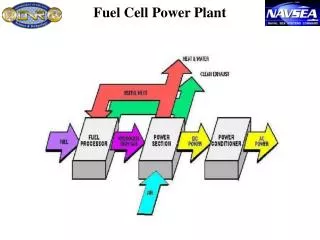
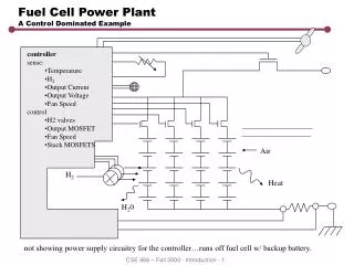
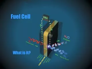
1st FCV - Shell’s Daf 44 (1960) Fuel Cells • Water, electrical energy and heat arise through the controlled combination of hydrogen and oxygen. • High efficiency, no (locally) harmful emissions, no moving parts—Long-term solution??
Polarization Curve i Fuel Cell Stack MEA Fuel Cell Tutorial, Los Alamos National Lab
Oxygen Hydrogen Pressure Current drawn from the traction motor and auxiliaries Temperature Humidity Fuel Cell Characteristics
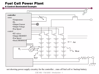
Reactant Flow Subsystem Excess Ratio = Supply/Use 1.2 for Hydrogen 2.0 for Oxygen Ist Provide sufficient reactant flow, fast transient response, minimize auxiliary power consumption
Heat & Temperature Subsystem Ist Fast warm-up, no temperature overshoot, low auxiliary fan and pump power
Water Management Subsystem Ist Maintaining membrane hydrated, balancing water usage/consumption
Power Management Subsystem Satisfactory vehicle transient response, assist fuel cell system
Literature Review - Model Types • Estimates of time constants for Subsystems • Electrochemistry O(10-19sec) • Electrode Membrane RC System O(Unknown) • Membrane Water Content O(Unknown) • Hydrogen & Air manifolds O(0.1 sec) • Flow Control & Supercharge Device O(1 sec) • Vehicle Dynamics O(100 sec) • Cell & Stack Temperature O(100sec) • Multi-Dimensional Fuel Cell Model • [Springer, 91, Nguyen, 93, Amphlett, 95, Dutta 01] • Model: Pressure, Partial Pressure, Temperature, Humidity Effects • Purpose: Design, Sizing • Dynamic Fuel Cell System Model • [Guzzella, 99, Hauer, 00, Boettner, 01, GCTool] • Model: Temperature, Pressure, Humidity Dynamics • Purpose: Transient Performance, System Efficiency • Steady-State Fuel Cell System Model • [… many…] • Model: Static Power and Efficiency maps • Purpose: Fuel Consumption, Hybridization
Reactant Supply System Goal: During fast current demands, providing sufficient reactant flow to achieve fast transient response, and reduce auxiliary power consumption
Compressor and Manifolds Model Compressor Supply Manifold Return Manifold
Stack Voltage Model • Cathode Mass Flow Model • Anode Mass Flow Model • Membrane Hydration Model Fuel Cell Stack Model
Stack State Equations Cathode Electrochemistry Anode Membrane mass transport
Membrane Hydration Model Water flow across membrane from anode to cathode = (Electro-osmotic drag) – (Back-diffusion) Current density Water molar flow rate through membrane Water Concentration mol/sec Diffusion coefficient Electro-osmotic coefficient Membrane water content
Voltage Model(Polarization) SAE 98C054 and personal communications with the authors: W-C Yang and J.A. Adams Pressure
Stack Voltage Model (Polarization) Pukrushpan et al, IMECE 2002
Net Power Oxygen Excess Ratio Ist Power Vcm Control Objectives pressure
Desired set-point Optimal Operating Points Steady-state lO2 andPnet for different Ist (using model) Net Power Oxygen Excess Ratio Gelfi et al, ACC 2003
Cancelation Controller c K (Ist)=w (Pnet)=z1 S (lO2)=z2 S (Vcm)=u Transient Interactions
Voltage should be used in the feedback Performance Tradeoff Varigonda et al, AICHE 2003
Closed Loop Bode Plots for Different Control Gains Power transients faster than 10 rad/s cause severe compromise to the FC Stack life due to O2 starvation Performance Tradeoff (cont.)
Overview --- How FC work? Modeling of Fuel Cell System Control of Oxygen Reactant Control of Fuel Processor for Hydrogen Reactant Experimental Setup Outline
On-board storage (“direct”) Cryogenic (liquid) hydrogen Liquifying hydrogen is expensive and storing this extremely cold fuel on a vehicle is difficult. Pressurized (gaseous) hydrogen Requires significant energy for compression, stringent safety precautions and bulky, heavy and expensive storage tanks. Metal hydride or Carbon nanofiber storage New technology far from commercial development. Onboard fuel processors (“reformer”) Convert hydrocarbon fuel, such as methanol or gasoline, to a H2 rich gas. Problem—Hydrogen Supply Adams et al., “The Development of Ford's P2000 Fuel Cell Vehicle,” SAE 2000-01-1061
Solar Hydrogen-on-Demand Direct H2 Electrolyser Fuel Processor Regenerative Source: Nature 414, 2001
Advantage: Widely Available, Inexpensive, Consumer Acceptance, Fuel Flexibility Liquid Fuels From Petroleum and/or Other Sources (e.g, Ethanol) Natural gas Large potential reserves, distributed worldwide H2 From Catalytic Partial OXidation (CPOX) Partial Oxidation: CH4 + 0.5O2 + Heat = CO +2 H2 (at 700o ) Total Oxidation: CH4 + 2O2 + Heat = CO2 +2 H2O Water-Gas Shift: CO + H2O = CO2 + H2 Autothermal point balances heat input/output 0.25-0.5 % (2500-5000 ppm) of CO remains in the feed Unacceptable performance if CO% is 0.001% (10ppm) Preferential Oxidation (PrOX) is needed!! Precise Control of O2 feed for the CO oxidation Any extra O2 will react with H2 (loss of fuel) On-Board Reforming
From Direct Hydrogen to Hydrogen-on-Demand When direct (stored) hydrogen is not available.... the Fuel Processor Control System becomes critical for efficiency, responsiveness and reliability.
From Direct Hydrogen to Reformate Hydrogen • H2 generation from Catalytic Partial OXidation (CPOX) • Partial Oxidation: CH4 + 0.5O2 + Heat = CO +2 H2 (at 700o ) • Total Oxidation: CH4 + 2O2 + Heat = CO2 +2 H2O • Goals: • Coordinate fuel (methane) and air flow to achieve • -- high conversion of H2 (regulate CPOX Temperature) • -- maximize H2 utilization
Integrated FPS+FCS+CBrn Burn the excess H2 (Catalytic burner) use the heat for (i) heating (or vaporizing) the fuel (ii) recover power throughTC Highly coupled system with non-minimum phase response very slow start-up Varigonda et al, AIChE 2003
Tcpox VH2 Baseline Controller Ist ublo uvlv Tcpox VH2
Tcpox VH2 Multivariable Controller Ist ublo uvlv Tcpox VH2 Pukrushpan et al, ACC 2003
Analysis of MIMO Controller VH2 C12 term is important Closed-loop step response Closed-loop frequency response
Multivariable Controller Coordination Ist ublo uval Tcpox VH2
Ist … The current command affects hydrogen… The error in hydrogen is detected by the controller through the C22 (typically a PI controller). The fuel valve tries to compensate for the detected hydrogen error … and causes a disturbance to the Tcpox through the P12 plant interaction Analysis of the FPS+FC Interaction Tcpox ublo S C11 S S S C22 S uvalve VH2
The Tcpox pertrubation Is detected by the PI controller in C11 ubl S S C11 That energizes the blower signal which eventually rejects the P12 disturbance. C12 … for faster response, one can use a direct command to the blower signal based on the fuel valve excursion. This is accomplished by the C12 term!! Analysis of the FPS+FC Interaction (cont.) … and causes a disturbance to the Tcpox through the P12 plant interaction Ist … Tcpox S S C22 S uvlv VH2
Adding Measurements from FPS Robustness+Performance Ist ublo uval ... Pprox Tcpox Pa VH2
Overview --- How it works? Modeling of Fuel Cell Control of Oxygen Reactant Control of Fuel Processor for Hydrogen Reactant Experimental Setup Outline
Answer: is between the ODE and the PDE world Attempt: Estimation of Hydrogen Starvation Question: Can we use the Fuel Cell Voltage to predict the hydrogen and oxygen content during typical flow, pressure, current transients?
Fuel Cell Control Test Station Designed by The Schatz Energy Research Center (SERC) Humboldt State University, Arcata, CA 1082 WE Lay Auto Lab
Air Hydrogen Current PEM Fuel Cell (2.4 kW) Water
Hydrogen Sensor Thermal Management Mass Air Controllers Hydrogen Storage and Pressure Regulation Data-Acquisition with LabView Controllable Load Fuel Cell Control Test Station 1082 WE Lay Auto Lab
Summary • Control of Fuel Cells • -- Stringent tradeoffs between net power response and oxygen supply • -- Estimation of hydrogen utilization with conventional sensors • Control of Fuel Processor (Hydrogen reformer) • -- Multivariable Control of Natural Gas and Air Flow Thanks to -- Scott Bortoff and Shubro Ghosh (UTRC and UTC-FC) -- W-C Yang and Scott Staley(Ford SRL and Th!nk) -- Charles Chamberlin, Peter Lehman (SERC) Sponsors: NSF and ARC (TACOM)
Thanks!!! Graduate Students Jay Pukrushpan Ardalan Vahidi UnderGraduate St. Marietsa Edje Dave Nay Visiting Students Sylvain Gelfi Denise McKay Thanks to Professor Peng