Download
1 / 10
100 likes | 334 Views
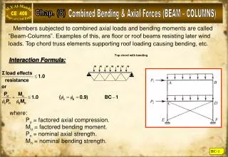
Top chord with bending. w w w w w w w. Combined Bending & Axial Forces (BEAM – COLUMNS). Chap. (8). Members subjected to combined axial loads and bending moments are called “Beam-Columns”. Examples of this, are floor or roof beams resisting later wind

E N D
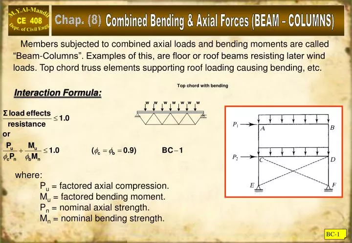
Top chord with bending w w w w w w w Combined Bending & Axial Forces (BEAM – COLUMNS) Chap. (8) Members subjected to combined axial loads and bending moments are called “Beam-Columns”. Examples of this, are floor or roof beams resisting later wind loads. Top chord truss elements supporting roof loading causing bending, etc. Interaction Formula: where: Pu = factored axial compression. Mu = factored bending moment. Pn = nominal axial strength. Mn = nominal bending strength. BC-1
LRFD Criteria for Beam – Column Equation (BC-1) is the basic of AISC design criteria as stated in (chapter H) of AISC – LRFD specs:- BC-2
LRFD Criteria for Beam – Column Example BC-1 The beam-column shown in Figure below is pinned at both ends and is subjected to the factored loads shown. Bending is about the strong axis. Determine weather this member satisfy the appropriate AISC Specification interaction equation. Solution From the column load tables (Table 4.1) the axial compressive design strength of W8x58 with Fy=50 ksi and KyLy=17 ft cPn = 286 kips BC-3
LRFD Criteria for Beam – Column (Contd.) From the beam design charts (Table 3-10 page 3 – 125) for un braced length of Lb=17, and Cb=1.0 bMn = 202 k.ft. For this condition and this loading : Cb=1.32 (table 3.1) bMn = 1.32 x 202 = 267 k.ft. bMp = 224 k.ft. (Table 3.2 page 3-18). bMn = 224 k.ft. bMp This member satisfies the AISC specifications. BC-4
Moment Amplification Moments caused by eccentricity of axial load cannot be ignored for beam-columns. The value of (P·) is called “Moment magnification” due to initial beam column initial crookedness or from bending due to transverse load (). It can be proven that a beam column with initial crookedness (e) and initial moment (Mo = Pu ·e), that the total moment becomes: M = Pu ( e + ymax) BC-5
Moment Magnification Contd. where:- M = Magnified moment. Mo = Initial moment (due to initial crookedness or more often due to transverse loads). Example BC-2 Compute the amplification factor for example (BC-1) So M = 1.15 Mo = 1.15 93.5 = 107.5 k·ft. BC-6
Braced Frames & Unbraced Frames • Moment amplification is covered in chapter C of the AISC code. • Two amplification factors are used in LRFD:- • * One to account for amplification due to deflection. • * One to account for amplification due to frame • sideway to lateral forces in unbraced frames. LRFD account for both effects: Mu = Mr = B1 Mnt + B2 Mlt AISC C2-1a Where: Mr = Mu = factored load combination as affected by amplification. Mnt = Maximum moment assuming no sidesway (no translation) Mlt = Maximum moment caused by sidesway (lateral translation). (Mlt = 0 for braced frames) B1 = amplification factor for braced frames. B2 = amplification factor for unbraced frames. BC-7
Members in Braced Frames The maximum moment in a beam-column depend on the end bending moments in a braced frame, the various cases are accounted for by a factor (Cm) as follows: (AISC C2-2) BC-8
Evaluation of Cm Factor Where: Cm = Coefficient whose value taken as follows: 1: If there are no transverse loads acting on the member, (AISC Equation C2 – 4) M1/M2 is a ratio of the bending moments at the ends of the member. M1 is the end moment that is smaller in absolute value, M2 is the larger, and the ratio is positive for moment bent in reverse curvature and negative for single-curvature bending. Reverse curvature (a positive ratio) occurs when M1 and M2 are both clockwise or both counterclockwise. BC-9
Evaluation of Cm Factor 2. For transversely loaded members, Cm can be taken as 0.85 if the ends are restrained against rotation and 1.0 if the ends are unrestrained against rotation (pinned). End restraint will usually result from the stiffness of members connected to the beam-column. The pinned end condition is the one used in the derivation of the amplification factor; hence there is no reduction for this case, which corresponds to Cm = 1.0. Although the actual end condition may lie between full fixity and a frictionless pin, use of one of the two values given here will give satisfactory results. (AISC C2 – 5) BC-10