Download
1 / 25
250 likes | 284 Views
This comprehensive guide delves into various aspects of image quality issues in visual displays, covering topics such as pixels, color representation, video formats, liquid crystal displays (LCDs), cathode ray tubes (CRTs), and projection displays. Key areas explored include screen resolution, intentional image degradation, brightness, color technologies, and display sensitivity to viewing angles. The text also discusses the technical intricacies of different display technologies and their impact on image clarity and fidelity. Gain valuable insights into enhancing visual experiences through a deeper understanding of display technologies with this informative resource.

E N D
Visual Displays Bowman, et al., pp. 29-59 Hodges and Babu 2011
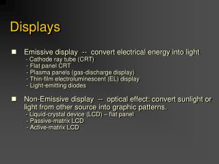
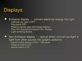
Outline • Image Quality Issues • Pixels • Color • Video Formats • Liquid Crystal Displays • CRT Displays • Projection Displays Hodges and Babu 2011
Image Quality Issues • Screen resolution • Color • Blank space between the pixels • Intentional image degradation • Brightness • Contrast • Refresh rate • Sensitivity of display to viewing angle Hodges and Babu 2011
Pixels • Pixel - The most basic addressable image element in a screen • CRT - Color triad (RGB phosphor dots) • LCD - Single color element • Screen Resolution - measure of number of pixels on a screen (m by n) • m - Horizontal screen resolution • n - Vertical screen resolution Hodges and Babu 2011
Other meanings of resolution • Pitch - Size of a pixel, distance from center to center of individual pixels. • Cycles per degree - Addressable elements (pixels) divided by twice the FOV measured in degrees. How much an eye can differentiate one object from another in terms of visual angles. • The human eye can resolve 30 cycles per degree (20/20 Snellen acuity). Hodges and Babu 2011
Color • There are no commercially available small pixel technologies that can individually change color. • Color is encoded by placing different-colored pixels adjacent to each other. • Field sequential color uses red, blue and green liquid crystal shutters to change color in front of a monochrome screen. Hodges and Babu 2011
Video Formats • NTSC - 525x480, 30f/s, interlaced • PAL - 625x480, 25f/s, interlaced • VGA - 640x480, 60f/s, non-interlaced • SVGA – 800x600, 60f/s non-interlaced • SXGA – 1280x1024, 60f/s non-interlaced • RGB - 3 independent video signals and synchronization signal, vary in resolution and refresh rate • Time-multiplexed color - R,G,B one after another on a single signal, vary in resolution and refresh rate • Hi-Def 1080p – 1900 x 1080, non-interlaced, widescreen aspect ratio 16:9, progressive scan Hodges and Babu 2011
Liquid Crystal Displays • Liquid crystal displays use small flat chips which change their transparency properties when a voltage is applied. • LCD elements are arranged in an n x m array called the LCD matrix • Level of voltage controls gray levels. • LCDs elements do not emit light, use backlights behind the LCD matrix Hodges and Babu 2011
LCDs (cont.) Hodges and Babu 2011
LCDs (cont.) • Color is obtained by placing filters in front of each LCD element • Usually black space between pixels to separate the filters. • Because of the physical nature of the LCD matrix, it is difficult to make the individual LCD pixels very small. • Image quality dependent on viewing angle. Hodges and Babu 2011
LCDs (cont.) LCD resolution is often quoted as number of color elements not number of RGB triads. Example: 320 horizontal by 240 vertical elements = 76,800 elements Equivalent to 76,800/3 = 25,500 RGB pixels "Pixel Resolution" is 185 by 139 (320/1.73, 240/1.73) Hodges and Babu 2011
LCDs (cont.) • Passive LCD screens • Cycle through each element of the LCD matrix applying the voltage required for that element. • Once aligned with the electric field the molecules in the LCD will hold their alignment for a short time • Active LCD screens • Each element contains a small transistor that maintains the voltage until the next refresh cycle. • Higher contrast and much faster response than passive LCD Hodges and Babu 2011
Advantages of LCDs • Flat • Lightweight • Low power consumption Hodges and Babu 2011
Cathode Ray Tubes (CRTs) Hodges and Babu 2011
Color CRT FLUORESCENCE - Light emitted while the phosphor is being struck by electrons. PHOSPHORESCENCE - Light given off once the electron beam is removed. PERSISTENCE - Is the time from the removal of excitation to the moment when phosphorescence has decayed to 10% of the initial light output. •Red, Green and Blue electron guns. •Screen coated with phosphor triads. •Each triad is composed of a red, blue and green phosphor dot. •Typically 2.3 to 2.5 triads per pixel. Hodges and Babu 2011
CRTs (cont.) • Strong electrical fields and high voltage • Very good resolution • Heavy, not flat Hodges and Babu 2011
Projection Displays • Use bright CRT or LCD screens to generate an image which is sent through an optical system to focus on a (usually) large screen. Hodges and Babu 2011
Projector Technologysee http://electronics.howstuffworks.com/projection-tv.htm • Two Basic Designs • Transmittive projectors - Shine light through the image-forming element (CRT tube, LCD panel) • Reflective projectors - Bounce light off the image-forming element (DLP) • In both types of projectors, a lens collects the image from the image-forming element, magnifies the image and focuses it onto a screen Hodges and Babu 2011
CRT Projectors CRT Based • One color CRT tube (red, blue, green phosphors) displays an image with one projection lens. • One black-and-white CRT with a rapidly rotating color filter wheel (red, green, blue filters) is placed between the CRT tube and the projection lens. • Three CRT tubes (red, green, blue) with three lenses project the images. The lenses are aligned so that a single color image appears on the screen. CRT-based projectors are usually heavy and large compared to other technologies Usually better range of color and brightness Hodges and Babu 2011
LCD Projectors • Use a bright light to illuminate an LCD panel, and a lens projects the image formed by the LCD onto a screen • Compact since LCD Chip small compared to CRTs • Less Heat, Less Power • Screen Door effect • One pixel can burn out • Different colors are polarized but not in the same orientation. Passive stereo polarization will not work. Hodges and Babu 2011
DLP (Digital Light Processing) Projectors • The Chip in a DLP Projector is a Digital Micromirror Device. • Essentially every pixel on a DMD Chip is a reflective mirror. • Higher resolution is possible than with LCD technology • No screen door effect. • Consistent Polarization • More expensive • Video Hodges and Babu 2011
Advantages/Disadvantagesof Projection Display • Very large screens can provide large FoV and can be seen by several people simultaneously. • Image quality can be fuzzy and somewhat dimmer than conventional displays. • Sensitivity to ambient light. • Delicate optical alignment. Hodges and Babu 2011
Displays in Virtual Reality • Head-Mounted Displays (HMDs) • The display and a position tracker are attached to the user’s head • Head-Tracked Displays (HTDs) • Display is stationary, tracker tracks the user’s head relative to the display. • Example: CAVE, Workbench, Stereo monitor Hodges and Babu 2011
Visually Coupled Systems A system that integrates the natural visual and motor skills of an operator into the system he is controlling. Basic Components • An immersive visual display (HMD, large screen projection (CAVE), dome projection) • A means of tracking head and/or eye motion • A source of visual information that is dependent on the user's head/eye motion. Hodges and Babu 2011
Differences HMD/HTD • HMD • Eyes are fixed distance and location from the display screen(s) • Line-of-sight of the user is perpendicular to the display screen(s) or at a fixed, known angle to the display screen(s). • Only virtual images in world • HTD • Distance to display screen(s) varies • Line-of-sight to display screen(s) almost never is perpendicular • Usually much wider FoV than HMD • Combines virtual and real imagery Hodges and Babu 2011