Download
1 / 38
380 likes | 381 Views
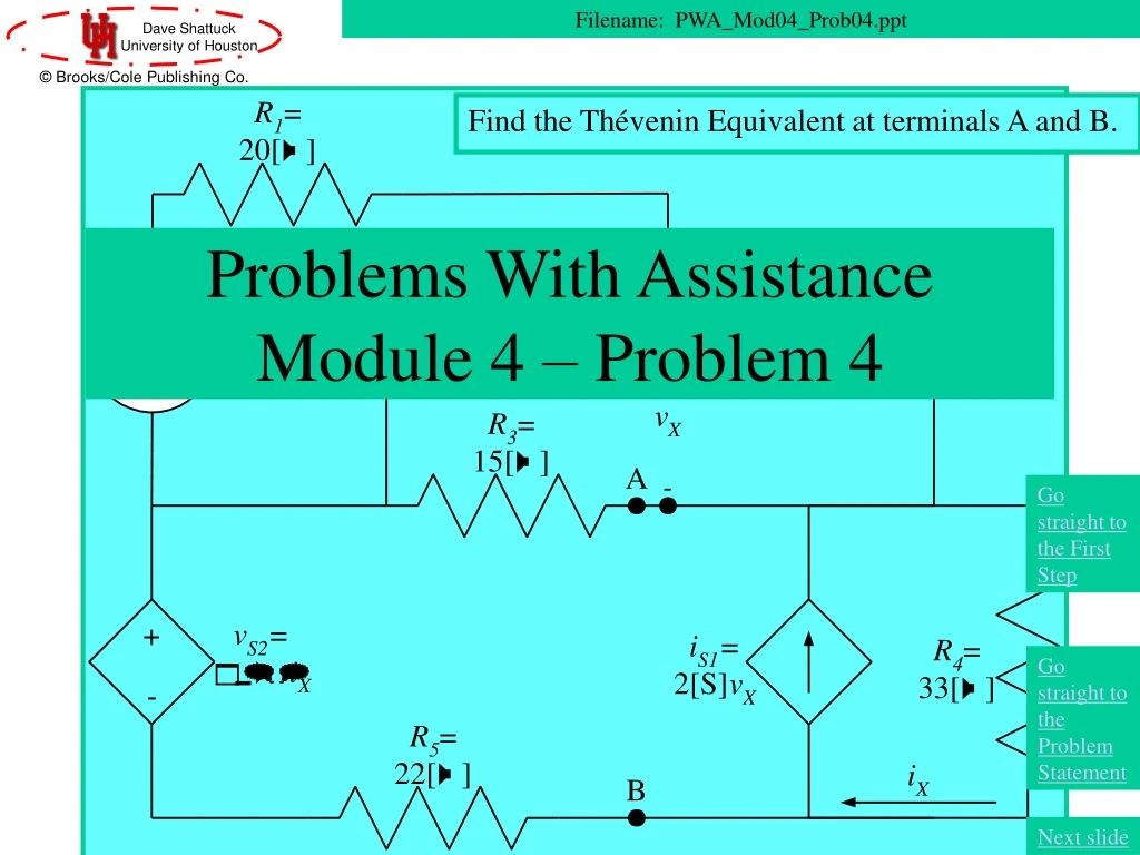
Find the Thévenin Equivalent at terminals A and B. Problems With Assistance Module 4 – Problem 4. Filename: PWA_Mod04_Prob04.ppt. Go straight to the First Step. Go straight to the Problem Statement. Next slide. Overview of this Problem. In this problem, we will use the following concepts:

E N D
Find the Thévenin Equivalent at terminals A and B. Problems With AssistanceModule 4 – Problem 4 Filename: PWA_Mod04_Prob04.ppt Go straight to the First Step Go straight to the Problem Statement Next slide
Overview of this Problem In this problem, we will use the following concepts: • Equivalent Circuits • Thévenin’s Theorem • Equivalent Resistance with Dependent Sources Go straight to the First Step Go straight to the Problem Statement Next slide
Textbook Coverage The material for this problem is covered in your textbook in the following sections: • Circuits by Carlson: Sections #.# • Electric Circuits 6th Ed. by Nilsson and Riedel: Sections #.# • Basic Engineering Circuit Analysis 6th Ed. by Irwin and Wu: Section #.# • Fundamentals of Electric Circuits by Alexander and Sadiku: Sections #.# • Introduction to Electric Circuits 2nd Ed. by Dorf: Sections #-# Next slide
Coverage in this Module The material for this problem is covered in this module in the following presentation: • DPKC_Mod04_Part04 Next slide
Problem Statement Find the Thévenin Equivalent at terminals A and B. Next slide
Solution – First Step – Where to Start? Find the Thévenin Equivalent at terminals A and B. How should we start this problem? What is the first step? Next slide
Problem Solution – First Step • How should we start this problem? What is the first step? • Define the open-circuit voltage. • Label the terminals of resistor R4 and remove it. • Define the short-circuit current. • Combine resistors R2 and R3 in parallel. • Combine resistors R1 and R2 in series. Find the Thévenin Equivalent at terminals A and B.
Your choice for First Step –Define the open-circuit voltage Find the Thévenin Equivalent at terminals A and B. This is a good choice for the first step. We could find the open-circuit voltage, and that will be the Thévenin voltage. We could also have solved for the short-circuit current first. Either is a reasonable first choice. Let’s define the open-circuit voltage, and then solve for it.
Your choice for First Step –Label the terminals of resistor R4 and remove it This is not a good choice for the first step. The resistor R4 is in parallel with the two terminals at which we are finding the equivalent. However, we are not finding the equivalent seen by R4, so this resistor will be a part of the equivalent. Thus, it needs to be left in place. Please go back and try again. Find the Thévenin Equivalent at terminals A and B.
Your choice for First Step –Define the short-circuit current This is a good choice for the first step. Since we are finding the Thevenin equivalent, we will eventually have to find the open-circuit voltage, or solve for it after finding the equivalent resistance. However, this is a very reasonable first choice. So, let’s label the short-circuit current and solve for it. Find the Thévenin Equivalent at terminals A and B.
Your choice for First Step was –Combine resistors R2 and R3 in parallel This is a good first step, but is not the choice that we would like to follow here, simply due to the approach we are going to take with this problem. Note that the resistors R2 and R3 are in parallel, and that combining them would not change the voltage vX that we need for the vS2 dependent source. This was a fine choice, but we would like for you to go back and try again. Find the Thévenin Equivalent at terminals A and B.
Your choice for First Step was –Combine resistors R1 and R2 in series This is not a good choice. The problem here is that resistors R1 and R2 are not in series, since they do not have the same current going through them. Please go back and try again. Find the Thévenin Equivalent at terminals A and B.
We have defined the open-circuit voltage, and called it vOC. In preparation for solving for this voltage, we have also chosen a reference node for the node-voltage method, and defined the other node voltage, vD. Note that there are only three essential nodes, so we will have two equations, plus two more for the dependent source variables. Thus we will need to write four equations. Let’s go to the next slide and write these equations. Defining the Open-Circuit Voltage and Solving for It Find the Thévenin Equivalent at terminals A and B. Next slide
Writing the Node-Voltage Equations We have written the four equations needed here. Let’s go to the next slide and simplify these equations. Find the Thévenin Equivalent at terminals A and B. Next slide
Simplifying the Node-Voltage Equations We canceled the last two terms of the second equation, and plugged the last two equations into the first two. Let’s go to the next slide and solve these equations. Find the Thévenin Equivalent at terminals A and B. Next slide
Solving the Node-Voltage Equations Find the Thévenin Equivalent at terminals A and B. When we take these two equations, and solve, we find that vOC = 0. Thus, the open-circuit voltage is zero. If you had chosen to find the short-circuit current, you would have found that iSC is also zero. Now, we have no choice but to find the equivalent resistance, REQ.
We have defined the short-circuit current, and called it iSC. In preparation for solving for this current, we have also chosen a reference node for the node-voltage method, and defined the other node voltage, vE. Note that there are only two essential nodes, so we will have one equations, plus two more for the dependent source variables, and once for iSC. Thus we will need to write four equations. Let’s go to the next slide and write these equations. Defining the Short-Circuit Current and Solving for It Find the Thévenin Equivalent at terminals A and B. Next slide
Writing the Node-Voltage Equations We have written the four equations needed here. Let’s go to the next slide and simplify these equations. Find the Thévenin Equivalent at terminals A and B. Next slide
Simplifying the Node-Voltage Equations We canceled the last two terms of the first equation, and plugged the last two equations into the first two. Let’s go to the next slide and solve these equations. Find the Thévenin Equivalent at terminals A and B. Next slide
Solving the Node-Voltage Equations Find the Thévenin Equivalent at terminals A and B. When we take these two equations, and solve, we find that iSC = 0. Thus, the short-circuit current is zero. If you had chosen to find the open-circuit voltage, you would have found that vOC is also zero. Now, we have no choice but to find the equivalent resistance, REQ.
Finding the Equivalent Resistance Find the Thévenin Equivalent at terminals A and B. • We wish to find the equivalent resistance, REQ. What should be our first step? • Combine resistors R2 and R3 in parallel. • Apply a test source. • Set independent sources equal to zero. • Set dependent sources equal to zero. • Set all sources equal to zero.
You Chose: Combine resistors R2 and R3 in parallel You said that the first thing to combine the parallel resistors. These resistors are in parallel, and they can be combined. Thus, this is a reasonable step, but taking this as the first step does not emphasize the very important step that we must always apply when finding the equivalent resistance. So, please go back and try again. Find the Thévenin Equivalent at terminals A and B.
You Chose: Apply a test source You said that the first thing would be to apply a test source. This is not correct. Applying a test source will be important here, but for this to work, we need to get rid of the independent sources. This is very important. Many students neglect this step, and get the wrong answer. Therefore we emphasize it by always performing it first. Let’s go back and try again. Find the Thévenin Equivalent at terminals A and B.
You Chose: Set independent sources equal to zero You said that the first thing to do was to set the independent sources equal to zero. This is the best first step. Always do this first, and you will not forget to do it. Let’s set the independent source, vS1, equal to zero. Find the Thévenin Equivalent at terminals A and B.
You Chose: Set dependent sources equal to zero You said that the first thing to do was to set the dependent sources equal to zero. This is incorrect. We do not set dependent sources equal to zero. We do set the independent sources equal to zero. Let’s do that. Go back and try again. Find the Thévenin Equivalent at terminals A and B.
You Chose: Set all sources equal to zero You said that the first thing to do was to set all of the sources equal to zero. This is incorrect. We do not set dependent sources equal to zero. We do set the independent sources equal to zero. Let’s do that. Go back and try again. Find the Thévenin Equivalent at terminals A and B.
Setting Independent Sources Equal to Zero We have set the independent source, vS1, equal to zero. Before going further, let’s simplify this circuit. The resistor R1 is in parallel with a short circuit, and will have no effect. It can be removed. The resistors R2 and R3 are in parallel, as many of you have already noted. Let’s go ahead and combine them in parallel, with a resistor R6. Note that the voltage vX is across this resistor. We make these simplifications in the next slide. Find the Thévenin Equivalent at terminals A and B. Next slide
What is the Next Step? • We have simplified the circuit. What is the next step to take? • Combine resistors R6 and R5 in series. • Apply a test source. • Simplify by setting iS1 equal to iX. Find the Thévenin Equivalent at terminals A and B.
You Chose: Combine resistors R6 and R5 in series You said that the first thing would be to combine resistors R6 and R5 in series. This is not a good thing to do. The resistors R6 and R5 are in series. However, if we did this, the voltage vX would no longer be present, and the iS1 dependent current source depends on vX. Let’s go back and try again. Find the Thévenin Equivalent at terminals A and B.
You Chose: Apply a test source You said that the first thing would be to apply a test source. This is the best choice for next step. Let’s apply a test source, between terminals A and B. Find the Thévenin Equivalent at terminals A and B.
You Chose: Simplify by setting iS1 equal to iX You said that the first thing would be to simplify by setting iS1 equal to iX. This is not a good thing to do. The current iX is not equal to iS1, as we will see when we begin writing equations. Let’s go back and try again. Find the Thévenin Equivalent at terminals A and B.
Applying a Test Source We have applied a test source, between terminals A and B. We chose a voltage source, because we thought that this would make the solution a little easier. A current source would have been nearly as good. We chose to give it a value, 1[V], just to make it easier to solve this with a typical calculator. The key is to find the ratio of vT/iT, since we have used the active sign convention to define iT. This ratio will give us REQ. Let’s solve. Find the Thévenin Equivalent at terminals A and B. Next slide
Writing Equations for iT Let’s solve. We apply KCL to the top essential node, and get Find the Thévenin Equivalent at terminals A and B. Next slide
Solving for iT To solve these equations for iT, we plug the last two equations into the first, and get Find the Thévenin Equivalent at terminals A and B. Next slide
Finding iT We plug in values and get Find the Thévenin Equivalent at terminals A and B. Next slide
Finding REQ Now we can solve for REQ and get Note that this value could be negative. For example, if we had defined vX with the opposite polarity, this answer would have been negative, with the value –2.74[W]. You could try it yourself. Find the Thévenin Equivalent at terminals A and B. Next slide
The Norton equivalent is a zero valued voltage source, in series with the equivalent resistance. This is, of course, just the resistance. Thus, we have the circuit drawn below. The Thevenin Equivalent Find the Thévenin Equivalent at terminals A and B. Go back to Problem Statement Go to Comments Slide
What Happened Here? • It seemed like a strange problem, with the open-circuit voltage and short-circuit current ending up as zero. Actually, if either is zero, the other will be zero. When there are no independent sources in the circuit, this will always happen. • Here in this problem, there was an independent source. However, if you look carefully you will note that that part of the circuit was shorted out, and had no effect on the rest of the circuit. This was clear from the node-voltage equations that we wrote to solve for iSC and for vOC. Note that in both cases the terms that included the independent source cancelled out. This is why the independent source seemed to not be there. Go back to Overviewslide.