Download
1 / 9
90 likes | 167 Views
An architecture for bridging multicast/broadcast-capable networks. Broadcast Internetworking. Yatin Chawathe yatin@research.att.com. Mukund Seshadri mukunds@cs.berkeley.edu. Jan 2002. Motivation. One-to-many or many-to-many ( broadcast ) applications are important

E N D
An architecture for bridging multicast/broadcast-capable networks Broadcast Internetworking Yatin Chawathe yatin@research.att.com Mukund Seshadri mukunds@cs.berkeley.edu Jan 2002
Motivation One-to-many or many-to-many (broadcast) applications are important No universally deployed multicast protocol. e.g. IP Multicast, SSM, Overlays, CDNs Typical problems Address-space scarcity (in IP Multicast) Limited scalability e.g. IP Multicast involves some form of flooding Need for administrative boundaries. Goal • Design an inter-domain multicast architecture for the composition of different, non-interoperable multicast/broadcast domains to provide an end-to-end multicast service.
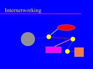
Architecture Source • Broadcast Network (BN) – any multicast capable network/domain/CDN) • Broadcast Gateway (BG) • Bridge between 2 BNs • Pre-configured peering relationship • BGs run overlay multicast-style algorithms. • Analogous to BGP routers. • App-level, for protocol-independence • Leverage solutions for availability and scalability • Less efficient link usage, and more delay • Inefficient processing Clients BG BN Peering Data
Naming • A session is associated with a unique Owner BN – • For shared tree protocols • Address space limited only by individual BNs’ naming protocols. • URL style- bin://Owner_BN/native_session_name?pmtr=value... • native_session_name - specific to the owner BN • pmtr – metrics of interest (latency, bandwidth, etc.) BIN Mediator (an abstraction) How does a client tell a BG that it wants to join a session? • A BG in a non-owner BN needs to be sent a JOIN message. • BNs are required to implement the BIN-Mediator, for sending JOINs for sessions. • Modified clients which send JOIN to BGs • Static pre-configured JOIN at the BG • Routers or other BN-specific aggregators
Routing • Same principles as BGP • Path – vector algorithm to propagate BG reachability info • Scope for forwarding policy hooks • The metric for cost determines the routes chosen • e.g. latency, bandwidth, BN-hop-count • Session-agnostic, in order to avoid all BNs knowing about all sessions. Routing Implementation • TCP used for routing exchanges. • Incremental updates • Route changes are propagated immediately • BG peering within a BN is constrained: Set of internal peering relationships should form a clique.
P1 (S1:L:P2) P2 (S1:P1:L) C1 P3 JOIN TRANSLATION Distribution Trees • One tree per session, reverse shortest path-tree rooted at owner BN. • BG tree state:(Session:Upstream node: list of downstream nodes) • Bidirectional • Non-optimal paths for sources not in owner BN • Avoids potentially large wide area latencies in sending data to the root. • Reduces 3rd party dependencies. Source P1 P1 (S1:L:P2) P2 P2 C1 JOINs (S1:P1:L,P3) C2 JOINs P3 P3 (S1:P2:P4) (S1:P3:L) L Local Multicast/Broadcast Interface C2 Client/BiN Mediator
SROUTE-- Session specific cost in the owner BN. Source • All BGs in the owner BN know all SROUTEs for owned sessions. • An SROUTE-Request to a BG in the owner BN elicits an SROUTE-Response, containing all the SROUTEs. • Downstream BGs can cache this value to reduce SROUTE traffic. • Downstream BG(s) compute best target BG in the owner BN and send JOINs towards that BG. • JOINs contain SROUTEs received earlier. • Increases initial setup latency, but reduces propagation of session info to disinterested BNs. JOIN SROUTE-Request SROUTE-Response REDIRECT TRANSLATION
JOIN TRANSLATION Data Paths (S1:L:P2) P1 • TRANSLATION messages carry data path addresses per session • e.g. a transit SSM network might require 2+ channels to be setup for one session. • Label negotiation, for fast forwarding. • Local Broadcast Interface • Send and Receive multicast data • Allocate and reclaim local multicast addresses • Subscribe to and unsubscribe from local multicast sessions • Get SROUTE values. Local session names are in TRANSLATION strings - interpreted only by the Local Broadcast Interface UDP:IP2,Port2 UDP:IP1,Port1 (S1:P1:L) P2 IPM:IPm1,Portm1 IPM:Null C1 IPM:Null P3 IPM:IPm1,Portm1
Event driven, user-level program Best-effort forwarding Deployed in 13-machine testbed Used simple HTTP-based CDN (servers) in each BN Performance improvement (e.g. faster forwarding) More Performance evaluation Scalability in number of domains – simulations? Transport-layer modules (e.g. SRM local recovery) With Rate-limited Server-- Preliminary Results Future Work With Rate-unlimited Server--