Download
1 / 1
10 likes | 105 Views
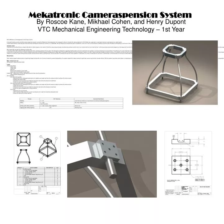
Mekatronic Cameraspension System. By Roscoe Kane, Mikhael Cohen, and Henry Dupont VTC Mechanical Engineering Technology – 1st Year. MCU (Mekatronic Cameraspension Unit) Project Outline

E N D
Mekatronic Cameraspension System By Roscoe Kane, Mikhael Cohen, and Henry Dupont VTC Mechanical Engineering Technology – 1st Year • MCU (Mekatronic Cameraspension Unit) Project Outline • A new self-leveling remote-controlled camera suspension system, named the Mekatronic Cameraspension Unit, designed to allow an industry film camera (planned for 300-500lbs max. capacity) to cross large chasms or open spaces via a cable system. • This will allow directors to get wide pan shots that would otherwise be precarious to achieve, or unobtainable. We are designing an inexpensive piece of equipment, so as not to rule out the business of starting young film buffs interested in participating in the fine art of film making. • Aesthetic Goals • In general we are selling this as a cheaper alternative to better designs on the market. We will be using cheap and easy manufacturing methods, and the look of our machine will not try to hide that fact. It will look professional and well designed, so that people will trust that it works, and the look should not instill in them worry that they are wasting their money on something worthless, but rather, the look should demonstrate that they are paying for functionality, not a fancy appearance. • More specifically, we plan the following to achieve this: • The arms will be CNC milled from plate stainless steel stock, sweeping upward to the top plate. This will appear professional, suggesting that this wasn't just some machine thrown together in someone's basement, but look efficient. The efficiency of curves is that they enclose a lot of space for their length. Also you avoid the potential weak points of corners. • Their will be a significant number of welds, probably ground down, and they will appear professional yet cheap. Again, this gives the feeling that the client is paying for results, not looks. These curved bars actually do help the function of the system and there will be no purely aesthetic components, and I expect no purely aesthetic features, at least in the physical structure. We haven't done any work on the software yet, but often software has aesthetic parts of it would appear very rough and poorly designed. Because of exposure to commercials, people are continually shown very aesthetic products which are relatively useless. I think that people have recognized these looks good but works bad sort of home use products. If this is so, then when professionally presented with something less pretty looking they might be willing to see it for what it is, and may look for value that it would have. Something well designed is often elegant in its own way, so while not pretty, I don't think our system will look ugly. • Most of our parts are clunky looking aluminum parts, and this has the effect of looking sturdy. They can see that it is sturdily built and won't even question if it will break. It's a chunk of metal after all. And even if it does break, it should be easy to fix as we are intentionally designing it to be easily disassembled. • Market Niche • Other camera support systems seem to target high budget movies with a lot of money to keep the camera held perfectly. Our system targets film makers looking to spend less money to get similar cinematic effects. With this system long shots can be taken in a warehouse or outdoors without the use of track or helicopter, and beyond the range of a cherry picker. Generally, this system will be cheaper to purchase and use than other methods capable of getting a comparable shot. • Major Components List • (All aluminum unless otherwise noted) • Cradle • Telescoping Shaft • Upper shaft • Lower shaft • Hitch pin • Bottom plate (welded to lower shaft) • Upper grip mount (welded to upper shaft) • Cable Grip – called okemo, found it was leitner/poma for their chair lifts distribution. • Spring washer dampening unit • Arm-assembly • Arm-assembly top plate • Legs are 2in by 3in rectangular tube stock cut to slightly over length and then the ends are milled to achieve the miter we want. • Smaller than bottom plate. • The parts to the mount block are milled from aluminum bar stock (all surfaces are machined). • Holes are made and tapped with a milling machine. • Arm-assembly bottom plate ( LU Control Box) • Legs are 2in by 3in rectangular tube stock cut to slightly over length and then the ends are milled to achieve the miter we want. • Larger than top plate. • The parts to the mount block are milled from aluminum bar stock (all surfaces are machined). • Holes are made and tapped with a milling machine. • Four arms • Attached to the mount blocks. • CNC machined, fillets done with a corner rounding end mill, made from stainless steel plate stock. • Holes are made with a milling machine.