Download
1 / 26
260 likes | 411 Views
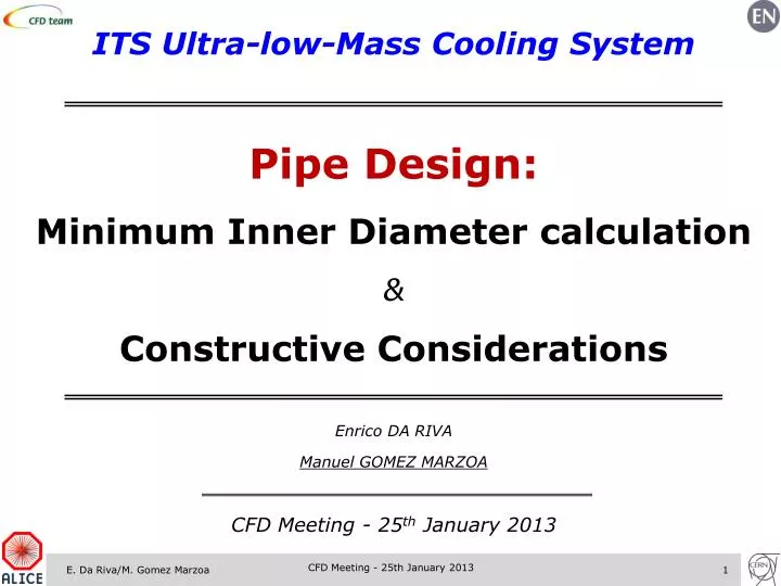
ITS Ultr a-low-Mass Cooling System Pipe Design: Minimum Inner D iameter calculation & Constructive Considerations. Enrico DA RIVA Manuel GOMEZ MARZOA CFD Meeting - 25 th January 2013. Contents. Overview Cooling system: constraints Cooling concepts Pipes per stave

E N D
ITS Ultra-low-Mass Cooling System Pipe Design: Minimum Inner Diameter calculation & Constructive Considerations Enrico DA RIVA Manuel GOMEZ MARZOA CFD Meeting - 25th January 2013 CFD Meeting - 25th January 2013
Contents • Overview • Cooling system: constraints • Cooling concepts • Pipes per stave • Operating pressure • Pipe Inner Diameter optimization • Inner Barrel layers • Outer Barrel layers • Construction of the tubing • Material • Erosion constraints • U-pipe construction CFD Meeting - 25th January 2013
Overview Inner Barrel Outer Barrel x/X0 < 0.3% per layer x/X0 < 0.8% per layer Wound-truss structure. Concept for outer layers (4-5, 6-7), based on the high-conductivity plate cooling idea. Wound-truss structure with high-conductivity plate. CFD Meeting - 25th January 2013
Cooling system: constraints • Refrigerant maximum velocity: • Avoiding failure by erosion. • Minimizing pressure drop. • No specific recommendations found for such small plastic pipe: • ASHRAE Handbook: not exceeding 1.5 m s-1 would minimize effects of erosion. • Catheters use similar pipes and materials. • 8.5 French gauge catheter (2.8 mm OD, ~1.5 mm ID) cordis/introducer 1. • Max. flow rate: 126 mL min-1 = 7.56 L h-1 = 1.18 m s-1 • Max. flow rate w/ p. bag @300 mmHg: 333 mL min-1=19.98L h-1 = 3.1 m s-1 • Damage by erosion in a plastic pipe could be roughly estimated by assessing the material hardness and compared to that of a regular copper pipe (but degradation?). • Admissible pressure drop: • Single-phase cooling: depends on the cooling system design. • Two-phase cooling: must be kept low to ensure the minimum ΔTSatacross stave. • Admissible ΔTRefrigerant across stave: • Related to stave temperature uniformity. • In a two-phase cooling system, should not decrease a lot (risk of going below dew point). 1Source: http://emupdates.com/2009/11/25/flow-rates-of-various-vascular-catheters/ CFD Meeting - 25th January 2013
Where are we? Inner Barrel • Successful proposal (up to 0.5 W cm-2) • Several prototypes for test: • Pipe ID = 1 mm • Squeezed pipes • K1100 Plate (λ ~ 1000 W m-1 K-1) No prototype performed OK (0.3 W cm-2) A last prototype with larger winding angle will be available for test CFD Meeting - 25th January 2013
Where are we? Inner Barrel • Pipe dimensions: • Initially: ID = 1.450, OD = 1.514 mm • Reason: winding CF around pipe without breaking it (wound-truss structure). • Used as well for the wound-truss structure with high conductivity plate. • Pipe ID could be reduced from the refrigerant viewpoint (water/C4F10). • Constructively possible in High-conductivity plate prototype! • Reduced pipe ID prototype: ID = 1.024, OD = 1.074mm: TO BE TESTED!! • Pipe ID optimization: consider: • Different cooling system layouts. • Refrigerants. • Pipe erosion. • Pipe material: • So far: only polyimide (Kaption®) has been taken into consideration and used for the construction of prototypes. • Concerns: • Pipe integrity? • Mechanical stiffness? (in case of making the U-bend without connectors). • … CFD Meeting - 25th January 2013
Cooling Concepts Inner Barrel Pipes per stave • 1 straight pipe along each stave: T1 T2 Stave ΔTRef-Stave = T3-T1 Stave T3 • U-pipe along each stave: T1 T2 = T1+0.5*ΔT Stave ΔTRef-Stave = T3-T1 T3 CFD Meeting - 25th January 2013
Cooling Concepts Inner Barrel Operating pressure • Water in single-phase flow: • Leak-less mode (p<1 bar):Δp at stave must be kept low! • No connectors:pMax and Δp limited by pipe strength. • C4F10in two-phase: • Main limitation is ensuring ΔTSat < ΔTSat-Admissibleacross the stave. Current design options • 6 possible designs. • 4 with water • 2 with C4F10 Water in single-phase orC4F10 two-phase. Leak-less or no connectors. Single pipe or U-pipe per stave. • Goal: assess the minimum pipe diameter for each of these designs. • Assuming reasonable operating conditions and respecting constraints. • Comparing with experimental results. CFD Meeting - 25th January 2013
Pipe Inner Diameter Optimization • Restrictions: • Single/U-pipe: • ΔTWater= 3-6 K • Lpipe= 0.29-0.58 m • Leak-less/no connectors: • ΔpMax-InOut= 0.2-2 bar Inner Barrel Water in single-phase • Assumptions: • Stave power density: 0.4 W cm-2 • Water maximum velocity: 1.5 m s-1 1,2. Water, single pipe: Water, U-pipe, leak-less: Water, U-pipe, no connectors: CFD Meeting - 25th January 2013
Pipe Inner Diameter Optimization Inner Barrel C4F10 in two-phase • Restrictions: • Single/U-pipe: • ΔTMax-InOut= 3-6 K • ΔpMax-InOut= 0.19-0.37 bar • Lpipe= 0.29-0.58 m • Assumptions: • Stave power density = 0.4 W cm-2 • ΔxInOut= 0.5 (conservative) • xAverage = 0.5 (for Friedel corr.) C4F10, single pipe: C4F10, U-pipe: CFD Meeting - 25th January 2013
Pipe Inner Diameter Optimization Inner Barrel SUMMARY • Restrictions: • ΔTMax-InOut= 3-6 K • Lpipe= 0.29-0.58 m • Assumptions: • Stave power density: 0.4 W cm-2 • The minimum pipe diameter is achieved for design number 4: • ID=0.55 mm ~ 62% smaller than current 1.45 mm ID! • Refrigerant material budget (i.e. water) is 7 times lower! CFD Meeting - 25th January 2013
Where are we? Outer Barrel Spaceframe Kapton, ID=2.794 mm wall= 0.06mm Carbonprepregthick=TBD CF Plate Carbonprepregthick=TBD Si 0.05mm thick Bus 30.4 mm CFD Meeting - 25th January 2013
Cooling Concepts Outer Barrel Pipes per stave • 1 straight pipe along each half stave: T1 T2 Half-stave ΔTRef-Stave = T3-T1 Half-stave T3 Stave • U-pipe along each half-stave: T1 Half-stave T2 = T1+0.5*ΔT T3 ΔTRef-Half-Stave = T3-T1 Half-stave CFD Meeting - 25th January 2013
Cooling Concepts Outer Barrel Operating pressure • Water in single-phase flow: • Leak-less mode (p<1 bar):Δp at stave must be kept low! • No connectors:pMax and Δp limited by pipe strength. • C4F10in two-phase: • Main limitation is ensuring ΔTSat < ΔTSat-Admissibleacross the stave. Current design options • 6 possible designs. • 4 with water • 2 with C4F10 Water in single-phase orC4F10 two-phase. Leak-less or no connectors. Single pipe or U-pipe per stave. • Goal: assess the minimum pipe diameter for each of these designs. • Assuming reasonable operating conditions and respecting constraints. • Comparing with experimental results (not yet). CFD Meeting - 25th January 2013
Pipe Inner Diameter Optimization • Restrictions: • Single/U-pipe: • ΔTWater= 3-6 K • Lpipe= 0.85-1.70 m • Leak-less/no connectors: • ΔpMax-InOut= 0.2-2 bar Outer Barrel Water in single-phase • Assumptions: • Stave power density: 0.4 W cm-2 • Water maximum velocity: 1.5 m s-1 L4-5 1,2. Water, single pipe per half stave: Water, U-pipe per half stave, leak-less: Water, U-pipe per half stave, no connectors: CFD Meeting - 25th January 2013
Pipe Inner Diameter Optimization Outer Barrel C4F10 in two-phase L4-5 • Restrictions: • Single/U-pipe: • ΔTMax-InOut= 3-6 K • ΔpMax-InOut= 0.19-0.37 bar • Lpipe= 0.85-1.70 m • Assumptions: • Stave power density = 0.4 W cm-2 • ΔxInOut= 0.5 (conservative) • xAverage = 0.5 (for Friedel corr.) C4F10, single pipe per half stave: C4F10, U-pipe per half stave: CFD Meeting - 25th January 2013
Pipe Inner Diameter Optimization Outer Barrel SUMMARY • Restrictions: • ΔTMax-InOut= 3-6 K • Lpipe= 0.85-1.70 m • Assumptions: • Stave power density: 0.4 W cm-2 L4-5 • The minimum pipe diameter is achieved for design number 4: • ID=1.71 mm ~ 39% smaller than the ordered 2.794 mm ID. CFD Meeting - 25th January 2013
Pipe Inner Diameter Optimization • Restrictions: • Single/U-pipe: • ΔTWater= 3-6 K • Lpipe= 1.5-3.0 m • Leak-less/no connectors: • ΔpMax-InOut= 0.2-2 bar Outer Barrel Water in single-phase • Assumptions: • Stave power density: 0.4 W cm-2 • Water maximum velocity: 1.5 m s-1 L6-7 1,2. Water, single pipe per half stave: Water, U-pipe per half stave, leak-less: Water, U-pipe per half stave, no connectors: CFD Meeting - 25th January 2013
Pipe Inner Diameter Optimization Outer Barrel C4F10 in two-phase L6-7 • Restrictions: • Single/U-pipe: • ΔTMax-InOut= 3-6 K • ΔpMax-InOut= 0.19-0.37 bar • Lpipe= 1.50-3.00 m • Assumptions: • Stave power density = 0.4 W cm-2 • ΔxInOut= 0.5 (conservative) • xAverage = 0.5 (for Friedel corr.) C4F10, single pipe per half stave: C4F10, U-pipe per half stave: CFD Meeting - 25th January 2013
Pipe Inner Diameter Optimization Outer Barrel SUMMARY • Restrictions: • ΔTMax-InOut= 3-6 K • Lpipe= 1.50-3.00 m • Assumptions: • Stave power density: 0.4 W cm-2 L6-7 • The minimum pipe diameter is achieved for design number 4: • ID=2.99 mm ~ 6.5% bigger than the ordered 2.794 mm ID. CFD Meeting - 25th January 2013
Pipe Inner Diameter Optimization 0.4 W cm-2 SUMMARY MAT. BUDGET CONSIDERATIONS • Achieving the target of 0.3%: • Use a two-phase flow. • Minimize pipe diameter to reduce the impact of the refrigerant to the global material budget. • BUT need to keep thermal contact between Si and pipe! • Constructive issues when ↓ID CFD Meeting - 25th January 2013
Construction of the tubing • General considerations: • Robust: elastic modulus, high burst pressure. • Thin walls:reduce mat. budget. • Compatible with refrigerant(C4F10). • Easy to bend:in case of making a no-connector stave, limited space. • Erosion:related to the material hardness. • Specific requirements: • High radiation hardness:minimum damage. • Ageing:physical and chemical stability over time. • Comply to LHC Fire Safety Instruction (IS-41) • Low material budget material (plastics better than metals). CFD Meeting - 25th January 2013
Construction of the tubing • General considerations: • Robust: • Tensile strength = 117.9 Mpa • Flexural Modulus = 4.1 GPa • Thin walls:down to 0.025 mm for a pipe with 0.55 mm ID • Compatible with refrigerant(C4F10): yes • Easy to bend: • Must avoid kinking failure: when section deforms to an elliptical shape. • A reinforcement braid can be included locally to prevent kinking. • Braid: SS or others, Covered with Nylon, Pebax… • Flexible liners like Nitinol (Ni + Ti) or Kevlar could reinforce the tube to be bent and preserve the shape (shape memory). • Erosion:related to the material hardness. • Polyimide/PEEK: 87D (Shore D) • PVC Pipe: 89D (Shore D) • Copper: 372 Mpa (Vickers) Minimum bend radius? In Vickers, polyimide would have 772 MPa CFD Meeting - 25th January 2013
Construction of the tubing • Specific requirements: • High radiation hardness:according to CERN-98-01 report, polymide: • No problem below 107Gy • Mild damage between 107 to5 107Gy • 1st layer of ITS Inner Barrel will be exposed to 700 krad/yr.=7000 Gy/yr. • Ageing:physical and chemical stability over time. • Plastic Pipe Institute states corrosion is not an issue in plastic pipes. • Comply to LHC Fire Safety Instruction (IS-41) • Polyimide is allowed. • Nylon® (polyamide) is allowed if a fire retardant NOT containing halogen, sulphuror phosphorus. • Pebax: polyether block amides – “legal” in cavern?? • Low material budget material (plastics better than metals). • Polyimide: X0 = 29 cm, minimum wall thickness is 0.025 mm. • PEEK: X0 = 31.45 cm, minimum wall thickness is 0.25 mm. CFD Meeting - 25th January 2013
Construction of the tubing • Advantages of a PEEK pipe over polyimide: • Low material budget material. • Polyimide: X0 = 29 cm • PEEK: X0 = 31.45 cm • The U-turn can be shaped and retain the shape. • Extremely stable. • More common in scientific applications than polyimide tubing. • Advantages of a polyimide pipe over PEEK: • Higher radiation hardness:according to CERN-98-01report. • Wall thickness: • Polyimide minimum wall thickness = 0.025 mm. • PEEK minimum wall thickness = 0.25 mm CFD Meeting - 25th January 2013
ITS Ultra-low-Mass Cooling System Pipe Design: Minimum Inner Diameter calculation & Constructive Considerations Enrico DA RIVA Manuel GOMEZ MARZOA CFD Meeting - 25th January 2013 CFD Meeting - 25th January 2013