Download
1 / 36
360 likes | 489 Views
progress in the simulation of Resistive Plate Chambers with multi-strip readout. Diego González-Díaz (GSI-Darmstadt). GSI, 10-02-09. acknowledgements. A. Berezutskiy (SPSPU-Saint Petersburg) G. Kornakov (USC-Santiago de Compostela), J. Wang (Tsinghua U.-Beijing)

E N D
progress in the simulation of Resistive Plate Chambers with multi-strip readout Diego González-Díaz (GSI-Darmstadt) GSI, 10-02-09
acknowledgements A. Berezutskiy (SPSPU-Saint Petersburg) G. Kornakov (USC-Santiago de Compostela), J. Wang (Tsinghua U.-Beijing) and the CBM-TOF collaboration
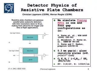
This is a talk about how to deal with signal coupling in highly inhomogeneous HF environments, electrically long and very long,not properly matchedand with an arbitrary number of parallel conductors. This topic generally takes a full book, so I will try to focus on theoretical results that may be of immediate applicability and on experimental results from non-optimized and optimized detectors.
The Compressed Baryonic Matter Experiment Transition Radiation Detectors Electro- magnetic Calorimeter Ring Imaging Cherenkov Detector Silicon Tracking Stations Projectile Spectator Detector (Calorimeter) Vertex Detector Dipole magnet Resistive Plate Chambers (TOF), more than 150m2, more than 100m2 require of strip-based coverage
huge cross-talk observed for timing RPCs with double-strip read-out A. Blanco et al. NIM A 485(2002)328 80-90% cross-talk levels cluster size: 1.8-1.9 !!!
but really... why?
definitions used here mirror electrode not counting Pad: set of 1+1(ref) conductors electrically small Multi-Pad: set of N+1(ref) conductors electrically small Strip: set of 1+1(ref) conductors electrically large Double-Strip: set of 2+1(ref) conductors electrically large Multi-Strip: set of N+1(ref) conductors electrically large This definition leads to: pad strip narrow-gap RPCs wide-gap RPCs
some of the geometries chosen by the creative RPC developers HADES-SIS FOPI-SIS ALICE-LHC -V -V V V -V -V STAR-RHIC -V -V V V ! V -V V -V V S. An et al., NIM A 594(2008)39 all these schemes are equivalent regarding the underlying avalanche dynamics... but the RPC is also a strip-line, a fact that is manifested after the avalanche current has been induced. And all these strip-lines have a completely different electrical behavior. HV filtering scheme is omitted
pad pad readout taking the average signal and neglecting edge effects induction signal collection if RinCg << 1/(α*vdrift) reasonable for typical narrow-gap RPCs at 1cm2 scale Rin D h Cg Rin Cg w
pad how to create a simple avalanche model We use the following 'popular' model • The stochastic solution of the avalanche equation is given by a simple Furry law(non-equilibrium effects are not included). • Avalanche evolution under strong space-charge regime is characterized by no effective multiplication. The growth stops when the avalanche reaches a certain number of carriers called here ne,sat that is left as a free parameter. • The amplifier is assumed to be slow enough to be sensitive to the signal charge and not to its amplitude. We work, for convenience, with a threshold in charge units Qth. 8.7 Raether limit space-charge regime ~7.5 ~7 log10 Ne(t) exponential-growth regime threshold ~2 exponential-fluctuation regime 0 to tmeas t avalanche Furry-type fluctuations the parameters of the mixture are derived from recent measurements of Urquijo et al. (see poster session) and HEED for the initial ionization
pad MC results. Prompt charge distributions for 'pad-type' detectors 1-gap 0.3 mm RPC standard mixture 4-gap 0.3 mm RPC standard mixture Eff = 74% Eff = 60% Eff = 38% simulated simulated measured qinduced, prompt [pC] qinduced, prompt [pC] measured assuming space-charge saturation at ne,sat= 4.0 107 (for E=100 kV/cm) Data from: P. Fonte, V. Peskov, NIM A, 477(2002)17. P. Fonte et al., NIM A, 449(2000)295. qinduced, total [pC]
MC results. Efficiency and resolution for 'pad-type' detectors
fine so far till here one can find more than a handful of similar simulations by various different groups, always able to capture the experimental observations. to the authors knowledge nobody has ever attempted a MC simulation of an 'electrically long RPC' why?
strip single-strip readout z y x transmission and signal collection induction Lo,L D Cg,L h Rin w
strip single-strip readout (with losses) At a given frequency signals attenuate in a transmission line as: they have little effect for glass and Cu electrodes as long as tan(δ)<=0.001 equivalent threshold ! ? ~ x 2/Texp(D/Λ) threshold log Ne(t) RL Lo,L to t Cg,L GL Rin
double-strip double-strip readout (signal induction) z y x strip cross-section for HADES-like geometry wide-strip limit h << w same polarity this yields signal induction even for an avalanche produced in the neighbor strip (charge sharing) opposite polarity! We use formulas from: D T. Heubrandtner et al. NIM A 489(2002)439 h extrapolated analytically to an N-gap situation and based on the Ramo theorem w
double-strip double-strip readout (transmission and signal collection) 0 low frequency term / 'double-pad' limit high frequency dispersive term It can be proved with some simple algebra that ict has zero charge when integrated over all reflections single-strip parameters double-strip parameters
double-strip double-strip (simulations) prototype 2002! input: signal induced from an avalanche produced at the cathode + FEE response signal transmitted normalized to the induced signal A. Blanco et al. NIM A 485(2002)328 cross-talk signal normalized to the signal transmitted in the main strip
double-strip double-strip (comparison with data)
multi-strip multi-strip A literal solution to the Transmission Line equations in an N-conductor Multi-TL is of questionable interest, although is a 'mere' algebraic problem. It is known that in general N modes travel in the structure at the same time. For the rest of the talk we have relied on the exact solution of the TL equations by APLAC (FDTD method) and little effort is done in an analytical understanding
multi-strip but how can we know if the TL theory works after all? A comparison simulation-data for the cross-talk levels extracted from RPC performance is a very indirect way to evaluate cross-talk. comparison at wave-form level was also done!
multi-strip far-end cross-talk in mockup RPC (23cm) signal injected with: trise~1ns tfall~20ns 50 50 anode 1 cathode 1 50 50 50 50 anode 2 cathode 2 50 50 50 50 anode 3 cathode 3 50 50 50 50 anode 4 cathode 4 50 50 50 50 anode 5 cathode 5 50 50
multi-strip near-end cross-talk in FOPI 'mini' multi-strip RPC (20cm) signal injected with: trise~0.35ns tfall~0.35ns cathode M. Kis, talk at this workshop 50 50 anode 0 50 50 anode 1 50 50 .......... 50 50 anode 11 50 50 anode 12 50 50 anode 13 50 50 anode 14 50 50 anode 15
multi-strip selected example of an optimized read-out structure as obtained in a recent beam-time at GSI
multi-strip 100cm-long shielded multi-strip experimental conditions: ~mips from p-Pb reactions at 3.1 GeV, low rates, trigger width = 2 cm (< strip width) long run. Very high statistics. ... ... 5x2 gaps RHV~10MΩ/
multi-strip double-hit in any of 3rd neighbors double-hit in any of 2nd neighbors double-hit in any of 1st neighbors no double hit 100cm-long shielded multi-strip time resolution for double-hits
multi-strip 100cm-long shielded multi-strip time resolution for double-hits tails
summary • We performed various simulations and in-beam measurements of Timing RPCs in multi-strip configuration. Contrary to previous very discouraging experience (Blanco, 2002) multi-strip configuration seems to be well suited for a multi-hit environment, if adequate 'a priori' optimization is provided. Cross-talk levels below 3% have been obtained, with a modest degradation of the time resolution down to 110 ps, affecting mainly the first neighbor. This resolution is partly affected by the poor statistics of multiple hits in the environment studied. • There is yet room for further optimization.
double-strip double-strip (optimization) fraction of cross-talk Fct: -continuous lines: APLAC -dashed-lines: 'literal' formula for the 2-strip case. a) original structure b) 10 mm inter-strip separation c) PCB cage d) PCB e) differential f) bipolar g) BW/10, optimized inter-strip separation, glass thickness and strip width. h) 0.5 mm glass. Shielding walls ideally grounded + optimized PCB
multi-strip 30cm-long differential and ~matched multi-strip experimental conditions: ~mips from p-Pb reactions at 3.1 GeV, low rates, high resolution (~0.1 mm) tracking 8 gaps Cm=20 pF/m ... ... Cdiff=23 pF/m Zdiff=80 Ω intrinsic strip profile is accessible! probability of pure cross-talk: 1-3% I. Deppner, talk at this workshop
Zc~18 Ω 35-cm long wide-strip, mirrored and shielded Cm experimental conditions: ~mips from p-Pb reactions at 3.1 GeV, low rates, trigger width = 2 cm (< strip width) BW=260 MHz Rin=100 Ω ... ... Cg little dispersive Fct=11% transverse scan 'fine-tunning' inter-strip region dominated by trigger width Fct=19% probability of pure cross-talk: 1-3% Analysis with high resolution tracking on-going.
MC results. Efficiency and resolution for 'pad-type' detectors
Parameters of the gas used for input: α* (effective Townsend coefficient), vd (drift velocity), no (ionization density) little dependence with mixture! no [mm-1] HEED (from Lippmann[4]) αextrapolated to mixture by using Freon's partial pressure: αmixture = αFreon(E/fFreon) fFreon *purely phenomenological! continuous line: data from Basurto et al. in pure Freon [5] vddirectly taken from Freon (inspired on microscopic codes) vd,mixture = vd,Freon
strip single-strip (HADES TOF-wall) - area 8m2, end-cap, 2244 channels - cell lengths D = 13-80 cm Zc = 5 - 12Ω (depending on the cell width) T = 0.2 - 0.4 v = 0.57c - disturbing reflections dumped within 50ns built-in electronic dead-time - average time resolution: 70-75 ps - average efficiency: 95-99% - cluster size: 1.023 D. Belver et al., NIM A 602(2009)687 A. Blanco et al., NIM A 602(2009)691 A. Blanco, talk at this workshop