Download

1 / 49
550 likes | 901 Views
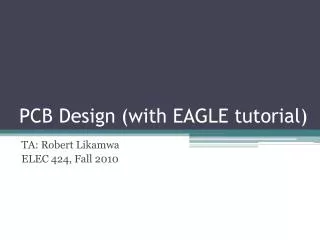
Using Eagle for PCB design Part 2, high speed mixed signal design techniques. Mike Twieg Case Western Reserve University November 21 st 2011. Overview. Wrap up from part 1: Exporting design files from Eagle, and submitting files for manufacturing Recommendations on SMT packages

E N D
Using Eagle for PCB design Part 2, high speed mixed signal design techniques Mike Twieg Case Western Reserve University November 21st 2011
Overview • Wrap up from part 1: Exporting design files from Eagle, and submitting files for manufacturing • Recommendations on SMT packages • High speed signal propagation • Mixed signal layout design • 4 layer design techniques
Design finishing checklist • Make sure the design rule checker (DRC) settings match the design for manufacture (DFM) rules for the manufacturer • No DRC errors (unless you are sure they are benign) • No outstanding ERC warnings. No design inconsistencies • No unrouted traces • Turn off all layers except “unrouted,” you should see nothing • If you intend to have a silkscreen printed: • You can export any layers to the silkscreen during the CAM process • Common layers: Names, values, place, docu
Gerber files Gerber is a common CAD format which describes images using vectors Industry standard is now RS-274X (extended Gerber format) Several Gerber files are needed, each having info from multiple layers in your layout editor Information on drill hits is not included in Gerber files. Excellon files contain drill coordinates and sizes.
The CAM processor The CAM processor is used to export the Gerber and Excellon files Open the CAM processor through the layout toolbar The CAM uses job files to perform specific tasks • Export Gerber files with gerb274x.cam • Export Excellon drill file with excellon.cam
Exporting Gerber files Each tab is a different Gerber file to be generated We highlight which layers in the layout editor are exported to each Gerber file Eagle does most of the work for us For two layer designs, we should only need to choose which layers to export to the silkscreen(s). Usually dimension, place, value, and/or docu layers. Make sure all the layers you want to export are enabled in the layout editor!!
Exporting Excellon drill file Now open up the job excellon.cam Exporting the Excellon file is even easier than the Gerber files Use default options, unless you really know what you are doing! Make sure all the layers you want to export are enabled in the layout editor!!
Preparing design files After running the gerb274x and excellon job files, you should end up with up to 9 files total with the following extensions • Filename.cmp (top copper layer) • Filename.sol (bottom copper layer) • Filename.stc (top soldermask layer) • Filename.sts (bottomsoldermask layer) • Filename.plc (top silkscreen layer) • Filename.pls (bottom silkscreen layer) • Filename.drd (excellon drill file) • Filename.dri (info on drill toolset – not needed) • Filename.gpi (general board info – not needed) Rename each file with its specific function, and put them all in one ZIP archive
Previewing Gerber files If you want to examine your Gerber files, you can use PentalogixViewmate. The free version allows you to easily view, but not edit, gerber files. Hint: if your drill data looks “exploded” when imported, check the settings on leading/trailing zeros
Submitting files for fabrication The steps for submitting files will depend heavily on the manufacturer It is highly recommended that you first use the manufacturer’s DFM (Design for Manufacturing) checker to check that your design conforms to their capabilities If you don’t pass their DFM checker, then you must change your DRC rules to be consistent We will be using Advanced Circuits as an example
Using Advanced Circuits First use the DFM checker at freedfm.com • When submitting the files for a DFM check, you will upload the zip file with your design • You must tell the DFM checker which file corresponds to which layer or function • You must also tell it some specifications of the design (number or layers, size, etc) • Submit the files and wait for results via email… If you pass the DFM checker, you may then submit the design for fabrication The process for ordering boards is almost identical to using the DFM checker, plus shipping and billing information
Using the DFM checker After submitting, you should receive an automated analysis from freeDFM.com, which includes two things of importance: • Plots layer review, which shows you PDF images of each layer • Any DFM errors found. All “show stoppers” should be fixed. Potential problems can often be left alone (especially ones relating to silkscreen layers) • If you pass the DFM check, then you can order the board for real. The process for ordering is almost exactly the same as for the DFM check.
Leaded IC packages 1.27mm (easy) 0.65mm (medium) 0.5mm (difficult) SSOP, QSOP MSOP, VSOP SOP, SOIC TQFP EQFP SOT23 SC70 SC75
Leaded IC packages 0.5-0.65mm (not too bad) 0.4-0.5mm (pretty hard) BGA (death is certain) QFN DFN Many varieties LFCSP
Two terminal packages For resistors/capacitors and inductors, 0805 is a good compromise between difficulty and density: For diodes, SOD123 and SOD323 are good choices: Often larger packages are needed in order to dissipate enough power or store more energy. Pay attention to component ratings!
High speed layout techniques Special care must be taken when designing PCBs for high speed digital communication and analog systems These techniques apply well to signals in the regime where transmission line effects are still negligible • 50mbps for digital data signals, 100MHz for analog • Remember, digital signals have bandwidths far above their baud rates! • Normally care about up to 5th-7th harmonics for data signals, 7th-9th harmonics for clock signals! First we look at how to preserve intentional signals
High speed signal propagation All high speed signals should be adjacent to at least one reference plane At high frequencies, currents in traces will return in any adjacent planes Cross section of microstrip trace Cross section of stripline trace
Return current paths Example: one microstrip trace with a source and a load ?
Return current paths At high frequencies, return currents want to form smallest loops Therefore they try to run underneath the signal traces Current distributions for high speed microstrip trace
Return current paths Return currents can be interrupted by split reference planes These large current loops will cause distortion and emit additional EMI!
Bypass capacitors Bypass capacitors are critical for keeping low loop areas and low impedances at high frequencies
Bypass capacitor selection For bypass caps to be effective: • Should be placed as close to the IC supply pins as possible • Use at least one per IC Capacitors are not perfect: self resonance • Can deal with self resonance by using several capacitors in parallel of different sizes • Smaller packages will have lower ESL, higher SRF
Stitching capacitors Can bridge plane splits with capacitors, allowing return currents to pass Thiswill reduce isolation between the two planes at HF. This is not wise, especially when crossing to or from analog partitions!
Signals changing layers Sometimes it is necessary to have a signal change layers with a via When this is done, the return current also changes layers! Need to provide a good path for the return current between layers • Use vias to locally connect the two planes • This only works when those two planes are actually the same potential!!
Signals changing layers When changing layers AND changing reference planes, we cannot use a via for return currents This is often the case with 4 layer board stackups (signal, GND, Vs, signal) We can use stitching caps to improve return currents Even so, this is a mess and is not suitable for very high speeds… Simply put, high speed signals should not change reference planes!
Differential signaling Differential signals use pairs of traces to form closed current loops Return currents on reference planes are greatly reduced Pairs must be routed close together to be effective Not a perfect solution: can still carry common mode return currents. Not the same as signal isolation!
When all else fails… If EMC/crosstalk performance is critical, then complete isolation may be necessary to cross splits Isolation can be optical or galvanic Basic optocoupler Digital magnetic coupler • Always some propagation delay, and limited bandwidth • Large packages, costly • Can be used for logic level translation • Very useful for interfacing to I/O ports where isolation is important
Mixed signal design Mixed signal design: any design where analog and digital systems operate in the same environment If you have a DAC or ADC in your design, it’s mixed signal. Power supplies may be considered analog systems Good mixed signal design is critical when digital and analog portions work at overlapping bandwidths
Mixed signal design goals Our goal is to prevent unintentional signals form causing interaction between digital and analog systems Interaction can be caused by conduction and field coupling Most basic rule is to spatially partition analog and digital sections Design example: ADS8329 16 bit ADC • 3.3V digital supply • 5.0V analog supply • 25MHz SPI interface • External analog shunt reference voltage • Use 9 pin header for digital signals and power supplies • Use edge SMC connector for analog signal in
Example Layout All high speed signals have their own return paths Reference is grounded on analog side Bypass caps close to supply pins Ferrite bead across split
Partitioning We can make multiple sub-partitions by making additional splits in the reference planes This can decrease crosstalk between analog channels
Partitioning We do not split the ground plane completely The analog and digital supply pins of ADCs/DACs must be kept close to the same potential Common practice is to join the supply planes only underneath the ADCs/DACs Signal traces may only cross between partitions at that point Q: Do we need completely different power supplies for different partitions? A: No, but we need to partition that power supply using split planes, ferrite beads, and bypass capacitors so that the two partitions do not share current paths at HF
Choking supplies Example: Using one regulator for both digital and analog partitions A ferrite bead provides HF current loops between the two partitions
Ferrite beads Capacitors are useful for encouraging HF current to flow along certain paths Ferrite beads are high impedances at HF, and prevent HF currents from flowing through them Ferrite beads are not inductors Both imaginary and real impedance increase with frequency, peak, and then decrease Forms damped resonances with bypass capacitors, so much less ringing
Considerations for SMPS Switch mode power supplies present great challenge Generate high dv/dt and di/dt, which causes lots of emissions Prevent B field emissions by minimizing loop areas Prevent E field coupling by screening with reference planes
Considerations for SMPS Switch mode power supplies present great challenge Generate high dv/dt and di/dt, which causes lots of emissions Prevent B field emissions by minimizing loop areas Prevent E field coupling by screening with reference planes Very high di/dt
Considerations for SMPS Switch mode power supplies present great challenge Generate high dv/dt and di/dt, which causes lots of emissions Prevent B field emissions by minimizing loop areas Prevent E field coupling by screening with reference planes Very high dv/dt Very high di/dt
Considerations for SMPS • High di/dt loop is minimized • Capacitive coupling from high dv/dt node may be an issue • Can use ground layer as a screen by putting other sensitive components on bottom side • Always best to move SMPS as far from analog circuitry as possible
Beyond two layers When it is not possible to adhere to good design techniques, you may need more layers Spacing between each layer may not be equal! Very important for high speed design. Distributed capacitance between inner reference layers is useful for high frequency bypassing • Common four layer stackup: • One inner layer is for ground plane(s) only. • Other inner layer is reserved for non-ground supply rails • Outer layers are for traces and components
Four layers Four layer designs have two key advantages • Separate layer for power supply routing • Both sides are freely available for components and signal traces This allows for much easier design and higher density However, in general, signalscannot change layers in this stackup without changing reference planes Properly guiding return currents across multiple reference planes is difficult Therefore, unless you do not need signals to change layers, four layer designs are not suitable for high frequency designs!
Six layers One common six layer stackup: equivalent to four layer stackup with two more outer signal layers added Signal layers 1 and 2 both use reference layer 3 for return Signal layers 5 and 6 both use reference layer 4 for return Traces on layer 1/6 run orthogonal to traces on layer 2/5, to reduce crosstalk
Six layers Another six layer stackup: equivalent to four layer stackup with two more inner signal layers added Signal layers 1 and 3 both use reference layer 3 for return Signal layers 4 and 6 both use reference layer 5 for return Traces on layers 3 and 4 should run orthogonal to prevent crosstalk
Conclusions Effective high layout design is all about controlling current paths • Intended current paths should be uninterrupted and low impedance • Unintended current paths should be minimized with proper partitioning and isolation Number of layers and stackup type will depend on design requirements • It is perfectly reasonable to have very high bandwidth systems on 2 layer boards. However, traces cannot cross or change layers easily • Moving to four layers allows more freedom for routing traces, on both sides, but traces still cannot change layers without risking signal integrity • In complex designs in which signal busses must cross, at least six layers will usually be necessary
Conclusions Proper mixed signal design is achieved by preventing shared current paths between analog and digital systems • Component placement is at least as important as signal routing • We do not use completely split ground planes, but rather partitioned planes which connect at specific locations • Multiple sub-partitions can be made by further dividing the reference planes • Analog and digital partitions can share supply rails, but care must be taken to introduce new high frequency current paths Any questions?