Download

1 / 16
390 likes | 1.65k Views
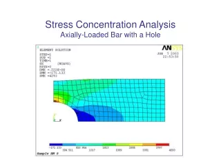
Axially loaded member. Axial load and normal stress under equilibrium load, Elastic Deformation. Saint-Venant’s Principle. Localized deformation occurs at each end, and the deformations decrease as measurements are taken further away from the ends

E N D
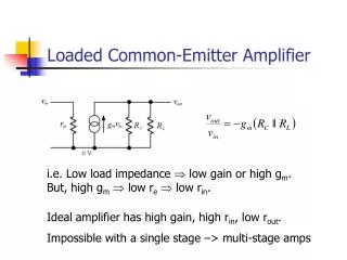
Axially loaded member Axial load and normal stress under equilibrium load, Elastic Deformation
Saint-Venant’s Principle • Localized deformation occurs at each end, and the deformations decrease as measurements are taken further away from the ends • At section c-c, stress reaches almost uniform value as compared to a-a, b-b • c-c is sufficiently far enough away from P so that localized deformation “vanishes”, i.e., minimum distance
Saint-Venant’s Principle • General rule: min. distance is at least equal to largest dimension of loaded x-section. For the bar, the min. distance is equal to width of bar • This behavior discovered by Barré de Saint-Venant in 1855, this the name of the principle • Saint-Venant Principle states that localized effects caused by any load acting on the body, will dissipate/smooth out within regions that are sufficiently removed from location of load • Thus, no need to study stress distributions at that points near application loads or support reactions
Elastic Deformation of an Axially Loaded Member Deformation can be calculated using SIGN CONVENTION When the member is tension When the member is compression
Elastic Deformation of an Axially Loaded Member Total deformation: The Above Figure:
Elastic Deformation of an Axially Loaded Member 1) Internal Forces 2) Displacement calculation
Example 1 Composite A-36 steel bar shown made from two segments AB and BD. Area AAB = 600 mm2and ABD = 1200 mm2. Determine the vertical displacement of end Aand displacement of B relative to C. A-36 Steel: E = 210 GPa
Displacement of point A Displacement of point B relative to C
Displacement of point A Displacement of point B relative to C
Solve it! The copper shaft is subjected to the axial loads shown. Determine the displacement of end A with respect to end D. The diameter of each segment are dAB = 75 mm, dBC= 50 mm and dCD = 25 mm. Take Ecu = 126 GPa.
1) Internal Forces 2) Displacement calculation Tension Tension P=20 kN PAB=30 kN PAB=30 kN PAB=30 kN PBC=10 kN Compression PCD=-5 kN P=5 kN Total deformation
Solve it! The assembly consist of three titanium (Ti-6A1-4V) rods and a rigid bar AC. The cross sectional area for each rod is given in the figure. If a force 30kN is applied to the ring F, determine the angle of tilt of bar AC.
FDC 1) Equilibrium Equation F= 30kN FAB 2) Based on FAB and FDC, FDC is predicted to deform more. dDC 3) Angle of tilt dAB Lecture 1
Example 2 The assembly shown in the figureconsists of an aluminum tube AB having a cross-sectional area of 400 mm2. A steel rod having a diameter of 10 mm is attached to a rigid collar and passes through the tube. If a tensile load of 80 kN is applied to the rod, determine the displacement of the end C of the rod. Take Est = 200 GPa, Eal = 70 GPa.
Find the displacement of end C with respect to end B. Displacement of end B with respect to the fixed end A, Since both displacements are to the right,