Download
1 / 43
430 likes | 554 Views
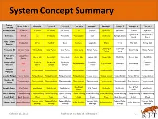
ISUAL System Design Summary. H. Heetderks / S. Harris. ISUAL Science objectives. Major Science objectives: 1. Determine the location and timing of luminous phenomena above thunderclouds to investigate their spatial, temporal and spectral properties.

E N D
ISUAL System Design Summary H. Heetderks / S. Harris
ISUAL Science objectives Major Science objectives: 1. Determine the location and timing of luminous phenomena above thunderclouds to investigate their spatial, temporal and spectral properties. 2. Obtain a global survey of upper atmospheric optical flash transients (sprites, elves, blue jets etc.) 3. Global observations of aurora and airglow NCKU UCB Tohoku ISUAL System Design Heetderks / Harris
ISUAL Science Operations Strategy • Instrument Mounted on ROCSAT2 S/C in 891 Km Polar Orbit • Science Data Collected on Night Side of Orbit • ROCSAT2 S/C reoriented to Point ISUAL at Limb or Somewhat Below at Beginning of Pass • Pointing may be Either Along the Track or Cross Track • Data are Stored and Compressed in on Board Memory and Transferred to the S/C Memory at the end of each Orbit • After 14 Orbits, the Data are Telemetered from the S/C Memory to the Ground NCKU UCB Tohoku ISUAL System Design Heetderks / Harris
ISUAL System Electrical Block Diagram NCKU UCB Tohoku ISUAL System Design Heetderks / Harris
ISUAL Instrument Complement • Sprite Imager • Gated Intensified CCD camera • 512 X 128 pixel resolution • 20 deg. X 5.0 deg. Field of View • Filter wheel has six selectable filters • Spectrophotometer • Six photometer modules are identical except for spectral characteristics • 20 deg. X 5.0 deg. Field of View • All photometers are boresighted in the same direction as the imager • All six channels are sampled at a 10 kHz rate NCKU UCB Tohoku ISUAL System Design Heetderks / Harris
ISUAL Instrument Complement (con’t) • Array Photometer • Two photometer units, identical except for optical filter bandpass • 20 deg. X 3.15 deg. FOV divided into 16 channels • Selectable sample rate • Boresight same as other instruments • Associated Electronics Package • Performs power distribution and control • Performs command decoding • Controls instrument and sensors • Performs compression of images • Stores 128 Mbytes in Mass Memory • Generates CCSDS telemetry packets NCKU UCB Tohoku ISUAL System Design Heetderks / Harris
Resource Requirements Summary -- Mass NCKU UCB Tohoku ISUAL System Design Heetderks / Harris
Resource Requirements Summary -- Power Typical Orbit: Mode 6 -- 40% Mode 5 -- 30% Mode 4 -- 30% * Gives 34.0 Watts Orbit Average (40.0 W Allocated) * Gives 44.1.0 Watts Peak (100.0 W Allocated) Note that the above assumes no heater power needed during science operations This is subject to change as a result of ongoing thermal analysis. NCKU UCB Tohoku ISUAL System Design Heetderks / Harris
ISUAL Sprite Imager MCP HV Supply Volume: ~250 H x 240 W x 362 L (mm) Max Power: 14.0 W Mass: 7.45 kg Filter Wheel Enclosure Front End Electronics (FEC) Input Collimator Phosphor HV Supply Filter Wheel Motor Daylight Sensor Lens Enclosure NCKU UCB Tohoku ISUAL System Design Heetderks / Harris
Imager Optical Path NCKU UCB Tohoku ISUAL System Design Heetderks / Harris
Optical Specifications • Filters • 1: 623 - 750 nm • 2: 762 nm • 3: 427.8 nm • 4: 630 nm • 5: 557.7 nm • 6: Open - Wideband NCKU UCB Tohoku ISUAL System Design Heetderks / Harris
CCD Active Area Masking • Imaging Earth Limb • Narrow, 4:1 Aspect Ratio • CCD Active Area • Mask applied to f/o taper • Size: 1024 x 256 (unbinned) • Size: 512 x 128 (binned) • FOV: 20° x 5º Top view of Dalsa CCD with f/o assembly Fiber Optic Taper Fiber Optic Window NCKU UCB Tohoku ISUAL System Design Heetderks / Harris
Imaging Modes • Aurora • Exposures taken continuously • Programmable exposure duration, relatively long (~1 sec) • Sprite Continuous • Exposures taken continuously • Programmable exposure duration, relatively short (~1 - 10 ms) • Programmable repetition period (~1 - 10 ms) • Images saved in Mass Memory, as Triggered by Event • Sprite Burst • Exposures taken in bursts of 8 images, Triggered by Event • Programmable exposure duration, very quick (~1 - 10 ms) See Document 8765-W7C for detailed information NCKU UCB Tohoku ISUAL System Design Heetderks / Harris
Frame Timing Example - Sprite Continuous ETRIG EXP FRMV Notes: 1. ETRIG signals the Sprite Event occurrence 2. Exposure duration (signal EXP) programmed by parameter ExpDuration 3. Frame repetition period programmed by parameter RepPeriod 4. Frame readout period (signal FRMV) is fixed, ~10 ms 5. Number of Pre- and Post-Event images programmed by NumPreTrig and NumPostTrig. Example Parameters: RepPeriod = 5 ms ExpDuration = 4.2 ms NumPreTrig = 1 NumPostTrig = 6 NCKU UCB Tohoku ISUAL System Design Heetderks / Harris
Imager Lens-CCD Assembly NCKU UCB Tohoku ISUAL System Design Heetderks / Harris
Imager Box/FEC Assembly NCKU UCB Tohoku ISUAL System Design Heetderks / Harris
Imager Filter Wheel/Housing Assembly NCKU UCB Tohoku ISUAL System Design Heetderks / Harris
Imager Assembly NCKU UCB Tohoku ISUAL System Design Heetderks / Harris
Spectrophotometer Description • Six Channels Identical except for Spectral Bandpass • 50 mm f/2 Lens • Aperture limits FOV to 20 deg X 5 deg • Uses Ruggedized EMR Photomultiplier Tubes • Individually Adjustable HV for each Unit • Six Co-aligned Modules Packaged with HV and Pre-Amps as one Unit • Remainder of Electronics contained in AEP NCKU UCB Tohoku ISUAL System Design Heetderks / Harris
Spectrophotometer - One Channel Input Collimator Stim LED PMT Insulating Sleeve Housing Lens Aperture Photomultiplier Tube Filter / Heater Ass’y NCKU UCB Tohoku ISUAL System Design Heetderks / Harris
Mechanical Layout of Complete Unit Optical Alignment Cube High Voltage Power Supply, Three per Side J5 - Spectrophotometer Power and Data Volume: ~187H x 156 W x 244 L (mm) Mass: 5.08 Kg Max Power: 6.8 W Single PMT Channel NCKU UCB Tohoku ISUAL System Design Heetderks / Harris
Photometer Module Assembly NCKU UCB Tohoku ISUAL System Design Heetderks / Harris
Spectrophotometer Assembly NCKU UCB Tohoku ISUAL System Design Heetderks / Harris
Mechanical Envelope of the Array Photometer Viewing Direction 238 mm Mass: 11.0 kg Max Power: 16.4 W 359 mm 236 mm NCKU UCB Tohoku ISUAL System Design Heetderks / Harris
Top View of the Array Photometer NCKU UCB Tohoku ISUAL System Design Heetderks / Harris
Side View of the Array Photometer NCKU UCB Tohoku ISUAL System Design Heetderks / Harris
Array Photometer Data Modes a. Sprite 1 Mode : S_MODE_SPRITE2 sampling rate=20KHz, fc(LPF)=10 KHz b. Sprite 2 Mode : S_MODE_SPRITE20 sampling rate=2KHz, fc(LPF)=10KHz c. Auroral Mode : S_MODE_AURORA sampling rate=200Hz, fc(LPF)=100Hz Science data format is 12 bits serial. Nominal DATA_CLK frequency is 5MHz. NCKU UCB Tohoku ISUAL System Design Heetderks / Harris
Functional Diagram for Array Photometer 8 ch 8 ch 8 ch 8 ch NCKU UCB Tohoku ISUAL System Design Heetderks / Harris
AP Trigger Sequence S_MODE_SPRITE2 S_MODE_SPRITE20 20KHz 20KHz 2 KHz 82 ms 18ms Triggered by Cloud Flash 18 ms Triggered by Sprites 10 ms NCKU UCB Tohoku ISUAL System Design Heetderks / Harris
AEP Mechanical Design • System Consists of Six Circuit Boards, each Surrounded by an Aluminum Frame • Low Voltage Power Converter is on top to conduct heat to thermal radiator • Power Controller, Data Processing Unit, Instrument Data Controller, Mass Memory, and Data Compression Module follow in order • Base Plate mounts unit to spacecraft deck • Electrical Connections made with Stacking Connector on each Board • Avoids need for Mother Board • Thermal Radiator attaches to feet on top of assembly • Walls of Frames are .200 inches thick to provide radiation shielding and a heat path to the thermal radiator • The Stack is held together with 10 Skewer Rods NCKU UCB Tohoku ISUAL System Design Heetderks / Harris
AEP Mechanical Assembly Max Power: 19.4 W Mass: 5.2 kg NCKU UCB Tohoku ISUAL System Design Heetderks / Harris
Exploded View of AEP Assembly Bottom Plate DCM Mass Memory Instr Data Controller DPU Power Controller LVPS NCKU UCB Tohoku ISUAL System Design Heetderks / Harris
Power System Block Diagram NCKU UCB Tohoku ISUAL System Design Heetderks / Harris
DPU Functions • Receives Commands • Sends Status • Manages Mass Memory • Manages Power System • Controls Telemetry from Mass Memory • Controls Imager • Controls Spectrophotometer • Commands Array Photometer • Manages Instrument Heaters NCKU UCB Tohoku ISUAL System Design Heetderks / Harris
DPU Block Diagram DPU Block Diagram SpacecraftInterface(RS-422) DPU Board 8085 CPU Science Telemetry Sci Telem To Imager MCP, Imager Phosphor, SP1-6 HVPS 4 PR HV Control (FPGA) SOH Telemetry Command Sts. 1 PR Daylight Sensor Command Rx Commands Diag. Port (EGSE) 1 PR To ImagerTo AP, SPTo DCM, PC Time Rx PPS CDI Sender 1 PR To ImagerTo SP 32 KB PROM STIM To DCM DCM Handshake 128 KB RAM 128 KB EEPROM To Mass Memory Mass Memory I/F NCKU UCB Tohoku ISUAL System Design Heetderks / Harris
Mass Memory Description • 2.6 GBits organized as 64 M x 40 bits • 32 bit data word after EDAC • 7 bit Error Correction Code per word corrects all single bit errors and detects all double bit and some multiple bit errors. • Base device is Samsung K4S560832A-TL1H 256 Mbit chip organized as 32M x 8bits. NCKU UCB Tohoku ISUAL System Design Heetderks / Harris
Mass Memory Interfaces IDC/ Mass Memory ACQUIRE Imager 12 DATA CLK DATA 2 SP CLK 2 STB 2 CTS Telemetry DATA-1 AP CLK DATA-2 DATA CLK RTS STB DATA DPU CMD0 CMD1 CLK 32 DATA DCM ADDR 26 MBUSY R/W 2 NCKU UCB Tohoku ISUAL System Design Heetderks / Harris
Mass Memory Block Diagram Imager Data Interface 32MB SDRAM 32MB SDRAM AP SP DPU 32MB SDRAM 32MB SDRAM DCM Level Shift TLM 32MB SDRAM 32MB SDRAM Address Interface 32MB SDRAM 32MB SDRAM Level Shift 32MB SDRAM 32MB SDRAM NCKU UCB Tohoku ISUAL System Design Heetderks / Harris
Usage Scheme A A • Circular buffers • Fill on trigger • M Pretrigger • N Posttrigger • Buffer switch Buffer Allocation M Trigger N B Buffer Allocation NCKU UCB Tohoku ISUAL System Design Heetderks / Harris
Data Compression Module Interface - Between DPU and DCM 1.DCM_BSY 2.DCM_ATN 3.CDI-CCLK 4.CDI-DAT 5.CDI-STB - Between MM and DCM 1. Address Bus (26bits) 2. Data Bus (32bits) 3. Read/Write enable 4. DMACK Image NCKU UCB Tohoku ISUAL System Design Heetderks / Harris
DCM Description • Loads program from Mass Memory (MM) • Receives commands from DPU via Mass Memory using MM Control Blocks (MMCB) • Reads Image data and Photometer data from MM and compresses both • Compressed data is stored in PVCF form in MM • Compression schemes: • Windowing region-of-interest in Images • Range coding using Predictor codes (similar to JPEG) NCKU UCB Tohoku ISUAL System Design Heetderks / Harris
Store 2 images IMAGE DATA Coding work flow Store Image Windowing image Sprite image yes No (windowing code) Coding Image (range code) IMAGE DATA Packet NCKU UCB Tohoku ISUAL System Design Heetderks / Harris