Download
1 / 72
1.11k likes | 2.11k Views
Mooring of ships - forces. Course no. 1. Purpose of mooring. To bring the ship alongside To keep the ship alongside To assist the ship when un-mooring. Design criteria of mooring configurations. Based on the forces acting upon the ship Wind Current Waves Swell

E N D
Mooring of ships - forces Course no. 1
Purpose of mooring • To bring the ship alongside • To keep the ship alongside • To assist the ship when un-mooring
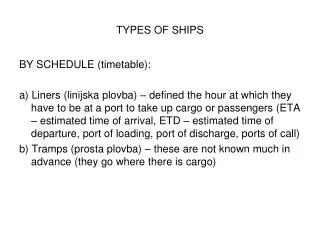
Design criteria of mooring configurations • Based on the forces acting upon the ship • Wind • Current • Waves • Swell • Other ships passing by (suction effect) • Location of the berth – Protected or sea berth • Types of ship – size, displacement, draught etc.
Example: Mooring of VLCC’s • Often moored outside the harbours along sea berths • Forces are so great that no winch is capable of bringing the ship alongside • Tugs are always used when mooring and leaving berth • The only criteria is the holding force of the winches • The ship must be maintained in position related to the shore manifold (chiksans)
Chicksan • One of the biggest problems with the fixed loading/discharging systems is the restricted liberty of movement of the ship • If one of the limits is breached => ESD-system activated
Different materials for ropes • Different configurations • All steel wire ropes (equipped or not equipped with tails) • All ropes are synthetic • Mixed systems (synthetic + steel wire rope) • New materials
Steel wire rope + tail • Purpose of the tail is to add elasticity to account for change in tidal heights • To protect against chafing cover splice of the tail with leather or plastic • The tail is connected to the steel wire rope by means of a Tonsberg shackle or a Mandal shackle • In case of frequent use tails are changed every 18 months
Tonsberg shackles Mandal Shackle
Synthetic mooring • Biggest problem is elasticity • It can give an important « sway » (balancer) to the ship (breaking out) • 3 mooring ropes – different materials – same length (50 m), MBL and load • Steel wire – 0.3m elongation • Polyprop – 5m elongation • Nylon – 8 m elongation
Synthetic mooring • A side effect is sagging • The « sag » is function of: • m-n • Weight of the mooring line • Tension in the line • Water depth (suction effect)
Mixed mooring systems • Mix of wire ropes and synthetic ropes • Certainly NOT the best configuration but the most common one. • If possible use steel wire rope as springs and breasts and use synthetic ropes as head- and stern line
New materials • Composite materials • Expensive but excellent mooring system • Kevlar –Aramid ropes are very strong, light and show little sagging. They react fast in case of breaking out of the ship.
Efficient mooring The efficiency of a mooring rope depends on the following factors • Material (steel wire or synthetic – elongation & MBL) • Length • Angles • in the horizontal plane • in the vertical plane
Function of the different ropes • Head- and stern lines & the springs are stabilising the ship alongside • Breast line will prevent the ship to break free from the berth • Breast lines must be as perpendicular as possible to the ships longitudinal axis • Springs must be as parallel as possible to the berth
Recommendations • The function of springs and breast lines is clear. • Springs are preventing longitudinal movement, while • Breast are opposing transversal movements. • The function of head and the stern lines depends on their angle with the longitudinal axis. • Great angle => they serve mainly as breast line while • Small angle => stopping longitudinal movement
The ideal configuration will rarely be achieved. • To obtain a perfect mooring configuration their must be a perfect harmony between the ships equipment , disposition on board and the configuration ashore • Berthing ships is always a matter of compromises
Following recommendations have been published by the OCIMF = Oil Company International Maritime Forum The recommendations are valid for a tanker moored alongside a T-berth
Recommendations based on OCIMF – Effective mooring • The horizontal angles of head-, stern- and breast lines < 15°
Recommendations based on OCIMF – Effective mooring • The vertical angle with the horizontal plane must be < 25° • The effective force is proportional to the cosine of the angle • If the angle is 25° the line is effective for 91% • If the angle is 45° the efficiency is reduced to 71% • => Springs & breasts must be long enough and not to steep
Recommendations based on OCIMF – Effective mooring • Breast lines are most effective is on the longitudinal axis. If is 45° we have to increase the force in the breast line till 141 ton to obtain an effective transversal force of 100 ton
Recommendations based on OCIMF – Effective mooring • Springs offer the greatest holding power in the longitudinal direction. Their length is 60 meters
Recommendations based on OCIMF – Effective mooring • The impact of the head and the stern lines on the total holding power of the mooring configuration is less important than the influence of springs and breasts. This mainly because these lines are too long. • Never the less they are important to compensate the dynamical forces.
Recommendations based on OCIMF – Effective mooring • Very short lines must be avoided. They always take the most important part of the load, especially when the ship is moving Short length = important vertical angle
Short breast lines • Long breast line: 52ton load is sufficient to obtain an effective holding power of 50 ton • Short breast line: Load has to be increased till 88 ton to obtain same result
Recommendations based on OCIMF – Effective mooring • All the mooring ropes in the same group (working in the same direction) must have the same tension. • If not, the weakest line will break first. Total load will have to be received by the remaining lines => increased risk of breaking (chain reaction) • Groups are aft spring + head lines, Stern lines + forward spring, breast lines
Recommendations based on OCIMF – Effective mooring • Their must be an equilibrium between the 4 groups: head- and stern lines, springs and breasts. Optimal mooring configuration is determined after studying the static and dynamical forces for a specific berth. Example: Proposed configuration (Direction of the wind: 110°) 4 breast lines (aft) + 1 stern line 3 headlines + 3 breast lines (fore)
Recommendations based on OCIMF – Effective mooring • The number of lines is function of the size of the ship and the prevailing weather conditions A – Panamax (75.000 dwt) - 12 lines (2 headlines – 4 breasts – 4 springs – 2 stern lines: 2 –2 – 2 fore and aft) B – VLCC (150.000 dwt) 16 lines (4 headlines – 4 breasts – 4 springs – 4 stern lines: 4 –2 – 2 fore and aft)
Mooring configurations bulk carriers • Cape Size: 4 –2 – 2 (fore and aft) • Panamamax: 4 –1– 1 (fore and aft) • Handy Size: 4 –1 (fore and aft) • Mini Bulker: 3 –1 (fore and aft) • Mini Bulker – moored so it can shift forward and backwards during loading/discharging
Recommendations based on OCIMF – Effective mooring • Mooring lines must be passed ashore using the deck fittings (fairleads) because of friction and the curvature relation. Curvature relation = curvature deck fitting/ mooring line
OCIMF equipment:Panamahawse- hole Pedestal Fairleads (Chaumard)
Info Suez & Panama Canal
Suez Canal • Total length is 190.25 km • Water surface width is 280.345 m • Width between the buoys is 195.215 m • Canal depth is 22.5 m • Maximum ship draught allowed is 62ft • Speed allowed for loaded carriers is 13 km/h • Speed allowed for unloaded carriers is 14 km/h. • Average transit time is 14 hours
Panama Canal • The Panama Canal is approximately 80 kilometers. • The Canal uses a system of locks • The locks function as water lifts: they raise ships from sea level (the Pacific or the Atlantic) to the level of Gatun Lake (26 meters above sea level)
Panama Canal • Each set of locks bears the name of the townsite where it was built: Gatun (on the Atlantic side), and Pedro Miguel and Miraflores (on the Pacific side). • The maximum dimensions of ships that can transit the Canal are: 32.3 meters in beam; draft 12 meters in Tropical Fresh Water; and 294.1 meters long • The narrowest portion of the Canal is Culebra Cut