Download
1 / 48
500 likes | 571 Views
This comprehensive guide covers binary digital transmission systems, intersymbol interference, and the significance of eye diagrams for system assessment. Explore how to achieve zero intersymbol interference and implement error control coding in digital carrier modulation schemes. Learn about line coding, equalization methods, and the impact of noise on system performance, with practical illustrations and explanations for each concept.

E N D
Digital Communications • Objectives • To describe a binary digital transmission system • To explain intersymbol interference • To show how an eye diagram is produced and explain its significance for system performance assessment • To show the pulses with zero intersymbol interference • To introduce the condition for zero intersymbol interference • To introduce the term “error probability” • To introduce the concept of error control coding • To introduce the concept of line coding and to provide illustrations of some practical line codes • To study digital carrier modulation schemes
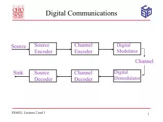
Digital Communications Recall that PAM is the simplest pulse modulation system, and can be used to get a complete digital system. PAM signals quantized coded PCM signal PCM signals consist ofbinary digits, i.e. a string of 1’s and 0’s. These binary digits are then transmitted over the transmission channel digital transmission
Digital Communications Binary digital transmission system • When the signal arrives at the output of the channel, it is • attenuated due to the lossand distorted due to limited bandwidth of the channel • The distortion can be partially corrected by the use of an equalizer.
Digital Communications Equalization A method of signal recovery is to use a filter that has a transfer function which is the reciprocal of the channel transfer function Q() So that the output spectrum G0() = G()Q()Heq() becomes G()/T. This technique of correcting the frequency response of a system for a known distortion is called equalization.
Digital Communications Equalization
Digital Communications Binary digital transmission system
Digital Communications Binary digital transmission system • Threshold device can restore the original signal, but the timing of the transitions may be irregular. • Causes of irregularity: • transition time varies withdifferent transmission channels • 2.threshold circuit may be corrupted by the noise • Thus,a clock waveform is extracted from the signal and used to retimethe data.
Digital Communications Intersymbol Interference In practice, the digital pulses are not perfectly rectangular and the transmission medium is neither perfectly linear nor distortionless (because it has limited bandwidth). A transmission channel has only limited bandwidth a small portion of signal spectrum is suppressed. signal spectrum distortion spreading of signal pulse (dispersion). Spreading of a pulse beyond its interval causes it interferes with neighboring pulses intersymbol interference (ISI).
Digital Communications Intersymbol interference
Digital Communications Is it is possible to obtain zero ISI with limited channel bandwidth? Condition for zero intersymbol interference (ISI) If the signal shape is p(t), then p(t) must satisfy p(0) = non-zero constant p(nT) = 0, when n 0. What kind of pulse shape satisfies the condition for zero ISI?
Digital Communications However, it is virtually impossible to achieve this kind of pulse shape in practice, as it is the impulse response of an ideal lowpass filter.
Digital Communications Both the intersymbol interference and noise may cause errors, and hence affect the system performance. How to evaluate the combination effect of noise and intersymbol interference on overall system performance? --- Use an eye pattern (eye diagram). The eye pattern is the synchronized superposition of all possible signal patterns obtained in a particular signal interval.
Digital Communications The eye pattern (eye diagram)
Digital Communications The interior region of the eye pattern is called the eye opening. (Eye opening is also the timing error allowed on the sampler at the receiver) Little ISI, little noise, little jitter more open eye An eye pattern provides useful information about the system performance.
Digital Communications The widthof the eye opening defines the time interval over which the received signal can be sampled without error from ISI. (The best sampling time: when the vertical opening of the eye is the largest) The height of the eye opening, at a specified sampling time, defines the system noise margin The slope of the open eye indicates the sensitivity to the timing error.
Digital Communications Probability of error in transmission In a binary digital communication system, the two levels (“1” and “0”) may be represented by A & 0 (unipolar binary signal) or A & - A (polar binary signal) In a polar binary signal transmission using pulse p(t), assumethat the binary levels at the receiver are - A and A. The observed waveform y(t) contains random noise n(t), so that y(t) = p(t) + n(t)
Digital Communicatins At a given time t1, the possible receiver inputs are A + n(t1) (signal present) or - A + n(t1) (signal absent) The detection threshold is 0, i.e. if the sample value > 0, the digit is detected as “1”; if the sample value < 0, the digit detected as “0”. There is a probability that the noise amplitude > signal amplitude, the erroroccurs when A + n(t1) is negative or – A + n(t1) becomes positive.
Digital Communications Distribution of signal + noise
Digital Communications Normally, the noise waveform has a Gaussian probability density function (pdf) where is the rms value of the noise amplitude. The probability of a one being interpreted as a zero (error): The probability of a zero being interpreted as a one (another error):
Digital Communications The total error probability is given by Pe = P(1) P(01) + P(0) P(10) where P(1) is the probability of a one being sent, and P(0) is that for a zero. Usually ones and zeros are equally likely, so P(0) = P(1) = ½. Substituting x = (y + A)/, and x = (y – A)/ respectively, we get where T(A/) is known as the Gaussian tail function (sometimes called the complementary error function).
Digital Communications Thus, Its values are given in tabular form in most mathematical handbooks. Alternatively, it is given in graph form as a function of the voltage SNR. A standard norm for Pe is 10-9, that is, if the transmission rate is 1 Gbit/s, there will be, on average, one error every second.
Digital Communications • In binary PCM, each sample of the signal is represented by a codewordof, say, k bits. These bits are transmitted. • Receiver is used to recognize each codeword in order to reconstruct the samples, but errors may occur in the transmission as a result of noise. • Ways to improve the reliability: • to increase the signal-to-noise ratio. • to use appropriate coding.
Digital Communications • Coding for digital transmission • Several techniques of coding for digital transmission • will be discussed • source coding • error control coding • line coding
Digital Communications Source Coding Concerning with how should source messages be represented using the minimum number of bits. Example: Encoding English text Seven bit ASCII (American Standard Code for Information Interchange) code Character Binary code Character Binary code Space 0100000 A 1000001 9 0111001 a 1100001
Digital Communications Error control coding In error control coding, the extradigits are introduced, in order to detect the presence of errors in the received pattern. Parity checks Sum check
Digital Communications Row and column parity check
Digital Communications • Line Coding • The digital data need to be coded into electrical pulses • for the purpose of transmission over the channel. This • process is called line coding or transmission coding. • There are two major categories of line codes: • return-to-zero (RZ), and • nonreturn-to-zero (NRZ). • With RZ coding, the waveform returns to a zero-volt • level for a portion (usuallyhalf) of the bit interval.
Digital Communications • Line coding is used to match the digital signal to the • physical characteristics of the channel (e.g. zero dc • content) and facilitate synchronization at the receiver. • a communication channel should not transmit dc components, as it is the waste of signal power. • In order to maintain synchronization, there should be enough timing information built into the code so that the clock signal can be easily exacted. A long series of binary 1s and 0s should not cause a problem in time recovery.
Digital Communications Unipolar code (on-off code) A “1” is transmitted by a pulse and a “0” is transmitted by no pulse. Polar code “1” is transmitted by a positive pulse p(t) and “0” is transmitted by a negative pulse – p(t). Bipolar code “0” is encoded by no pulse and “1” is encoded by a pulse p(t) or – p(t), depending on whether the previous “1” is encoded by p(t) or – p(t). In short, pulse representing consecutive 1’s alternate in sign. This format has zero dc level (assuming an equal number of 1s and 0s).
Digital Communications The nonreturn-to-zero (NRZ)format is disadvantages because it has a dc component and does not allow for self-clocking. The NRZ-bipolar (NRZ-B)format eliminates the dc component (assuming that an equal number of 1s and 0s occur) but it is also not self-clocking. The polar return-to-zero (RZ) format includes clock information, has zero dc level (again, for equal numbers of 1s and 0s), but has three voltage levels (for bipolar).
Digital Communications Manchester code A “1” is represented by a “1” level during the first half-bit interval, then shift to “0” levelfor the latter half-bit interval; a “0” is indicated by the reverse representation. Manchester code uses a level transition of one direction or the other in the middle of every bit interval. This provides the receiver with clocking information and produces a zero dc level even if the 1s and 0s are not equal.
Digital Communications The output of a PCM system is a string of 1’s and 0’s. If they are transmitted over the transmission medium such as the copper wire, they can be directly transmitted as two voltage levels + V and – V, if a polar code is adopted. This is baseband digital transmission, the signals are transmitted at their baseband frequency.
Digital Communications If digital signals are to be transmitted over a bandpass channel by use of high frequency carrier wave such as signal transmission throughspace using antenna, some form of modulation has to be used. This is referred to bandpass digital transmission.
Digital Communications Digital carrier modulation There are three basic forms of digital modulation, corresponding to AM, FM and PM are known as amplitude-shift keying (ASK), frequency-shift keying (FSK), and phase-shift keying (PSK), in which the amplitude, frequency or phase of the sinusoidal carrier is switched between either of two values corresponding to a 1 or a 0.
Digital Communications Amplitude Shift Keying (ASK) In ASK, the modulated signal can be expressed as Note that the modulated signal is still an on-off signal. Thus, ASK is also known as on-off keying (OOK).
Digital Communications Frequency Shift Keying (FSK) In FSK, the modulated signal can be expressed as
Digital Communications Phase Shift Keying (PSK) In PSK, the modulated signal can be expressed as
Digital Communications Digital carrier demodulation The detection of digital carrier modulation systems is virtually identical to that of analog modulation systems, i.e. the coherent demodulation method is used. OOK signals can be demodulated also by using an envelope detector.
Questions (Digital Communications) • Questions • What is intersymbol interference? How is it generated? • What is eye diagram? What is its application? • What pulse shape has zero intersymbol interference? • What is the condition for zero intersymbol interference? • How are the two levels, “1” and “0”, represented in unipolar binary signal and in polar binary signal respectively? • What is the main advantage of source coding? • How bit streams are electrically represented in communication systems? • What are suitable methods to transmit PCM signals through space using antenna?
Exercise Problems (Digital Communications) 1. A digital transmission system employs a signal element waveform at the input to the decision circuit given by p(t) = (1 – cos2t/T) / 2(t/T)2 Show that this provides zero ISI for a binary signalling rate of 1/T bits/s.
Exercise Problems (Digital Communications) 2. Consider a source which produces message based on three symbols: A, B, C. The symbols are found to occur, on average, with relative frequencies A = 0.5, B = 0.25, C = 0.25. It is required to encode messages in a binary format; two coding schemes are proposed: Scheme1: A = 01, B = 10, C = 11 Scheme2: A = 1, B = 01, C = 00 Show that, on average, a smaller number of bits per message are required for scheme 2 than for scheme 1.
3. (a) The overall transfer function of a transmission medium is given as Ha(w). The inverse Fourier transform of this function is • If the sequence of pulses, shown below, is to be transmitted through the • medium given above, discuss whether there will be any possibility of • error due to intersymbol interference at the receiver. Explain. (Hint: • there is an inverse time-bandwidth relationship, i.e. B ~ 1 /τ, whereτis • pulse duration) (b) If we now send the same sequence of pulses through another transmission medium which has the transfer function Hb(w) shown below, will there be intersymbol interference? Explain.