Download
1 / 36
360 likes | 480 Views
Distributed File Systems. Distributed file system ( DFS ) – a distributed implementation of the classical time-sharing model of a file system , where multiple users share files and storage resources. A DFS manages set of dispersed storage devices

E N D
Distributed File Systems • Distributed file system (DFS) – a distributed implementation of the classical time-sharing model of a file system, where multiple users share files and storage resources. • A DFS manages set of dispersed storage devices • Overall storage space managed by a DFS is composed of different, remotely located, smaller storage spaces. • There is usually a correspondence between constituent storage spaces and sets of files.
Naming and Transparency • Naming– mapping between logical and physical objects. • Multilevel mapping – abstraction of a file that hides the details of how and where on the disk the file is actually stored. • A transparent DFS hides the location where in the network the file is stored. • For a file being replicated in several sites, both the existence of multiple copies and their location are hidden.
Naming Structures • Location transparency – file name does not reveal the file’s physical storage location. • File name still denotes a specific, although hidden, set of physical disk blocks. • Convenient way to share data. • Can expose correspondence between component units and machines. • Location independence – file name does not need to be changed when the file’s physical storage location changes. • Better file abstraction. • Promotes sharing the storage space itself. • Separates the naming hierarchy from the storage-devices hierarchy.
Naming Schemes — Three Main Approaches • Files named by combination of their host name and local name; guarantees a unique systemwide name. • Attach remote directories to local directories, giving the appearance of a coherent directory tree; only previously mounted remote directories can be accessed transparently (NFS). • Total integration of the component file systems. • A single global name structure spans all the files in the system. • If a server is unavailable, some arbitrary set of directories on different machines also becomes unavailable.
Remote File Access • Reduce network traffic by retaining recently accessed disk blocks in a cache, so that repeated accesses to the same information can be handled locally. • If needed data not already cached, a copy of data is brought from the server to the user. • Accesses are performed on the cached copy. • Files identified with one master copy residing at the server machine, but copies of (parts of) the file are scattered in different caches. • Cache-consistency problem – keeping the cached copies consistent with the master file.
Cache Location – Disk vs. Main Memory • Advantages of disk caches • More reliable. • Cached data kept on disk are still there during recovery and don’t need to be fetched again. • Advantages of main-memory caches: • Permit nodes to be diskless. • Data can be accessed more quickly. • Performance speedup in bigger memories. • Server caches (used to speed up disk I/O) are in main memory regardless of where user caches are located; using main-memory caches on the user machine permits a single caching mechanism for servers and users.
Cache Update Policy • Write-through – write data through to disk as soon as they are placed on any cache. Reliable, but poor performance. • Delayed-write – modifications written to the cache and then written through to the server later. Write accesses complete quickly; some data may be overwritten before they are written back, and so need never be written at all. • Poor reliability; unwritten data will be lost whenever a user machine crashes. • Variation – scan cache at regular intervals and flush blocks that have been modified since the last scan. • Variation – write-on-close, writes data back to the server when the file is closed. Best for files that are open for long periods and frequently modified.
Consistency • Is locally cached copy of the data consistent with the master copy? • Client-initiated approach • Client initiates a validity check. • Server checks whether the local data are consistent with the master copy. • Server-initiated approach • Server records, for each client, the (parts of) files it caches. • When server detects a potential inconsistency, it must react.
Caching vs Remote Service • In caching, many remote accesses handled efficiently by the local cache as fast as local ones. • Servers are contacted only occasionally in caching • Reduces server load and network traffic. • Enhances potential for scalability. • Remote service method handles every remote access across the network • penalty in network traffic, server load, and performance. • Total network overhead in transmitting big chunks of data (caching) is lower than a series of responses to specific requests (remote-service). • Caching is superior in access patterns with infrequent writes. • Benefit from caching when execution carried out on machines with either local disks or large main memories. • Remote access on diskless, small-memory-capacity machines should be done through remote-service method.
Stateful File Service Mechanism • Client opens a file. • Server fetches information from its disk, stores it in its memory, and gives the client a connection identifier unique to the client and the open file. • Identifier is used for subsequent accesses until the session ends. • Server must reclaim the main-memory space used by clients who are no longer active. Increased performance. • Fewer disk accesses. • Stateful server knows if a file was opened for sequential access and can thus read ahead the next blocks.
Stateless File Server • Avoids state information by making each request self-contained. • Each request identifies the file and position in the file. • No need to establish and terminate a connection by open and close operations.
Stateful vs Stateless Service (1) • Failure Recovery. • A stateful server loses all its volatile state in a crash. • Restore state by recovery protocol based on a dialog with clients, or abort operations that were underway when the crash occurred. • Server needs to be aware of client failures in order to reclaim space allocated to record the state of crashed client processes (orphan detection and elimination). • With stateless server, the effects of server failure and recovery are almost unnoticeable. A newly reincarnated server can respond to a self-contained request without any difficulty.
Stateful vs Stateless Service (2) • Penalties for using the robust stateless service: • longer request messages • slower request processing • additional constraints imposed on DFS design • Some environments requirestateful service. • A server employing server-initiated cache validation cannot provide stateless service, since it maintains a record of which files are cached by which clients. • UNIX use of file descriptors and implicit offsets is inherently stateful; servers must maintain tables to map the file descriptors to inodes, and store the current offset within a file.
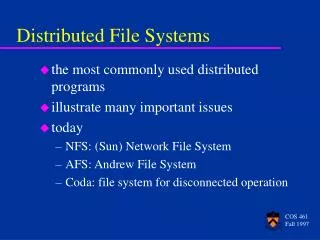
The Sun Network File System (NFS) • An implementation and a specification of a software system for accessing remote files across LANs (or WANs). • The implementation is part of the Solaris and SunOS operating systems running on Sun workstations using an unreliable datagram protocol (UDP/IP protocol and Ethernet).
NFS (Cont.) • Interconnected workstations viewed as a set of independent machines with independent file systems, which allows sharing among these file systems in a transparent manner. • A remote directory is mounted over a local file system directory. The mounted directory looks like an integral subtree of the local file system, replacing the subtree descending from the local directory. • Specification of the remote directory for the mount operation is nontransparent; the host name of the remote directory has to be provided. Files in the remote directory can then be accessed in a transparent manner. • Subject to access-rights accreditation, potentially any file system (or directory within a file system), can be mounted remotely on top of any local directory.
NFS (Cont.) • NFS is designed to operate in a heterogeneous environment of different machines, operating systems, and network architectures; the NFS specifications independent of these media. • This independence is achieved through the use of RPC primitives built on top of an External Data Representation (XDR) protocol used between two implementation-independent interfaces. • The NFS specification distinguishes between the services provided by a mount mechanism and the actual remote-file-access services.
Mounting in NFS Mounts Cascading mounts
NFS Mount Protocol • Establishes initial logical connection between server and client. • Mountoperation includes name of remote directory to be mounted and name of server machine storing it. • Mount request is mapped to corresponding RPC and forwarded to mount server running on server machine. • Export list – specifies local file systems that server exports for mounting, along with names of machines that are permitted to mount them. • Following a mount request that conforms to its export list, the server returns a file handle— a key for further accesses. • File handle – a file-system identifier, and an inode number to identify the mounted directory within the exported file system. • The mount operation changes only the user’s view and does not affect the server side.
NFS Protocol • Provides a set of remote procedure calls for remote file operations. The procedures support the following operations: • searchingfor a file within a directory • reading a set of directory entries • manipulating links and directories • accessingfile attributes • reading and writing files • NFS servers are stateless; each request has to provide a full set of arguments. • The NFS protocol does not provide concurrency-control mechanisms.
Three Major Layers of NFS Architecture • System call layer - UNIX file-system interface (based on the open, read, write, and close calls, and file descriptors). • Virtual File System (VFS) layer – distinguishes local files from remote ones, and local files are further distinguished according to their file-system types. • The VFS activates file-system-specific operations to handle local requests according to their file-system types. • Calls the NFS protocol procedures for remote requests. • NFS service layer – implements the NFS protocol.
NFS Path-Name Translation • Performed by breaking the path into component names and performing a separate NFS lookup call for every pair of component name and directory vnode. • To make lookup faster, a directory name lookup cache on the client’s side holds the vnodes for remote directory names.
NFS Remote Operations • Nearly one-to-one correspondence between regular UNIX system calls and the NFS protocol RPCs (except opening and closing files). • NFS adheres to the remote-service paradigm, but employs buffering and caching techniques for the sake of performance. • File-blocks cache – when a file is opened, the kernel checks with the remote server whether to fetch or revalidate the cached attributes. Cached file blocks are used only if the corresponding cached attributes are up to date. • File-attribute cache – the attribute cache is updated whenever new attributes arrive from the server. • Clients do not free delayed-write blocks until the server confirms that the data have been written to disk.
ANDREW FILE SYSTEM • A distributed computing environment under development since 1983 at Carnegie-Mellon University. • AFS features a uniform name space, location independent file sharing • Andrew is highly scalable; the system is targeted to span over 10000 workstations. • Andrew distinguishes between client machines (workstations) and dedicated server machines.
ANDREW (Cont.) • Clients are presented with a partitioned space of file names: a local name space and a shared name space. • Dedicated servers, called Vice, present the shared name space to the clients as an homogeneous, identical, and location transparent file hierarchy. • The local name space is the root file system of a workstation, from which the shared name space descends. • Workstations run the Virtueprotocol to communicate with Vice, and are required to have local disks where they store their local name space. • Servers collectively are responsible for the storage and management of the shared name space.
Servers supply three main services: • True vice file server, responsible of managing a local collection of files ( user level process) • a trusted authentication server • Update and consistency processes
Communication: AFS uses RPCs • RPC2 offers reliable RPCs using unreliable UDP protocol • Side effect is a mechanism that permits client server comm. using application specific protocol (RPC2 characteristic) . • RPC2 offers support for multicasting (useful for stateful servers)
ANDREW (Cont.) • Clients and servers are structured in clusters interconnected by a backbone LAN. • A cluster consists of a collection of workstations and a clusterserver and is connected to the backbone by a router. • A key mechanism selected for remote file operations is whole file caching. Opening a file causes it to be cached, in its entirety, on the local disk.
ANDREW Shared Name Space • Andrew’s volumesare small component units associated with the files of a single client or user. • A fid identifies a Vice file or directory. A fid is 96 bits long and has three equal-length components: • volume number • vnode number – index into an array containing the inodes of files in a single volume. • uniquifier – allows reuse of vnode numbers, thereby keeping certain data structures, compact. • Fids are location transparent; therefore, file movements from server to server do not invalidate cached directory contents. • Location information is kept on a volume basis, and the information is replicated on each server.
Naming Clients in AFS have access to a single shared name space.
ANDREW File Operations • AFS caches entire files from servers. A client workstation interacts with Vice servers only during opening and closing of files. • Venus – caches files from Vice when they are opened, and stores modified copies of files back when they are closed. • Reading and writing bytes of a file are done by the kernel without Venus intervention on the cached copy. • Venus caches contents of directories and symbolic links, for path-name translation. • Exceptions to the caching policy are modifications to directories that are made directly on the server with responsibility for that directory.
ANDREW Implementation • Client processes are interfaced to a UNIX kernel with the usual set of system calls. • Venus carries out path-name translation component by component. • The UNIX file system is used as a low-level storage system for both servers and clients. The client cache is a local directory on the workstation’s disk. • Both Venus and server processes access UNIX files directly by their inodes to avoid the expensive path name-to-inode translation routine.
ANDREW Implementation (Cont.) • Venus manages two separate caches: • one for status • one for data • LRU (least recently used) algorithm used to keep each of them bounded in size. • The status cache is kept in virtual memory to allow rapid servicing of stat (file status returning) system calls. • The data cache is resident on the local disk, but the UNIX I/O buffering mechanism does some caching of the disk blocks in memory that are transparent to Venus.