Download
1 / 1
10 likes | 128 Views
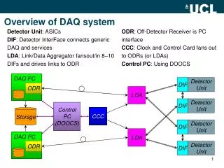
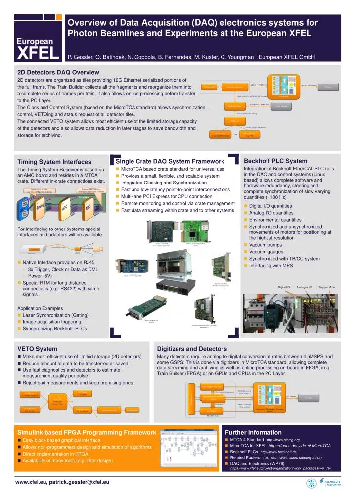
8 bussed M-LVDS lines, for triggers, clocks and interlocks. Radial clocks to AMC, Low jitter, configurable direction. Overview of Data Acquisition (DAQ) electronics systems for Photon Beamlines and Experiments at the European XFEL. Backplane. AMC Timing. MCH. AMC ADC. AMC ADC. Cross-

E N D
8 bussed M-LVDS lines, for triggers, clocks and interlocks Radial clocks to AMC, Low jitter, configurable direction Overview of Data Acquisition (DAQ) electronics systems for Photon Beamlines and Experiments at the European XFEL Backplane AMC Timing MCH AMC ADC AMC ADC Cross- Point-Switch Data Data Cross- Point-Switch Trigger Trigger Interlock Interlock VETO User e.g. Digitizer VETO Source 1 e- or Photon Diagnostic VETO Unit Configurable Decision Matrix P. Gessler, O. Batindek, N. Coppola, B. Fernandes, M. Kuster, C. Youngman European XFEL GmbH … VETO Source N Fast Detector Clock and Control For 2D Detectors Front-end electronics Detector Head 2D Detectors DAQ Overview 2D detectors are organized as tiles providing 10G Ethernet serialized portions of the full frame. The Train Builder collects all the fragments and reorganize them into a complete series of frames per train. It also allows online processing before transfer to the PC Layer. The Clock and Control System (based on the MicroTCA standard) allows synchronization, control, VETOing and status request of all detector tiles. The connected VETO system allows most efficient use of the limited storage capacity of the detectors and also allows data reduction in later stages to save bandwidth and storage for archiving. … … Train Builder Front-end electronics PC Layer Optical – 10G Ethernet Optical – 10G Ethernet Detector Head RJ45 – clock, START/STOP, VETO, Status Clock and Control Timing Receiver Differential – Trigger, clock Optical - 2.5Gb/s low-latency VETO Unit Optical - 2.5Gb/s low-latency VETO Source Avalanche Photo Diode VETO Sources (e.g. TPS) … VETO System • Make most efficient use of limited storage (2D detectors) • Reduce amount of data to be transferred or saved • Use fast diagnostics and detectors to estimate measurement quality per pulse • Reject bad measurements and keep promising ones Beckhoff PLC System Integration of BeckhoffEtherCAT PLC rails in the DAQ and control systems (Linux based) allows complete software and hardware redundancy, steering and complete synchronization of slow varying quantities (~100 Hz) Digital I/O quantities Analog I/O quantities Environmental quantities Synchronized and unsynchronized movements of motors for positioning at the highest resolution Vacuum pumps Vacuum gauges Synchronized with TB/CC system Interfacing with MPS Timing System Interfaces The Timing System Receiver is based on an AMC board and resides in a MTCA crate. Different in-crate connections exist. For interfacing to other systems special interfaces and adapters will be available. • Native Interface provides on RJ45 • 3x Trigger, Clock or Data as CML • Power (5V) • Special RTM for long distance connections (e.g. RS422) with same signals Application Examples • Laser Synchronization (Gating) • Image acquisition triggering • Synchronizing Beckhoff PLCs Single Crate DAQ System Framework MicroTCA based crate standard for universal use Provides a small, flexible, and scalable system Integrated Clocking and Synchronization Fast and low-latency point-to-point interconnections Multi-lane PCI Express for CPU connection Remote monitoring and control via crate management Fast data streaming within crate and to other systems … Clock & Control RTM (University Collage London) DAMC2 – Universal digital AMC (DESY) Timing System (Stockholm University / DESY) Timing Cable (3x Trigger/Clock/Data and Power) Trigger, Clock or Data Timing Receiver Level Converter (e.g. to TTL) External System (e.g. Camera) MicroTCA Crate SIS8300 – ADC AMC (Struck Innovative Systems) Digital I/O Analogue I/O Stepper Motor MicroTCA Carrier Hub (N.A.T.) High-performance DSP and FPGA board (DMCS/DESY) Digitizers and Detectors Many detectors require analog-to-digital conversion of rates between 4.5MSPS and some GSPS. This is done via digitizers in MicroTCA standard, allowing complete data streaming and archiving as well as online processing on-board in FPGA, in a Train Builder (FPGA) or on GPUs and CPUs in the PC Layer. Train Builder Concentration, Reorganization, Processing (Optional) In-Crate FPGA/DSP Card 10G/1G Ethernet or Other protocol Point-to-point (low-latency) Digitizer PC Layer 10G Ethernet Digitizer Timing Receiver PCI Express 10G/1G Ethernet or Other protocol In-Crate CPU MircoTCA Crate Simulink based FPGA Programming Framework • Easy block based graphical interface • Allows non-programmers design and simulation of algorithms • Direct implementation in FPGA • Availability of many tools (e.g. filter design) Further Information • MTCA.4 Standard http://www.picmg.org • MicroTCA for XFEL http://doocs.desy.de MicroTCA • Beckhoff PLCs http://www.beckhoff.de • Related Posters: 131, 150 (XFEL Users Meeting 2012) • DAQ and Electronics (WP76) https://www.xfel.eu/project/organization/work_packages/wp_76/