Download
1 / 3
30 likes | 115 Views
1. 2. 3. 4. 5. 6. 7. 8. 9. 10. 11. 12. 13. 14. 15. cm. Crystal development. Reproducible growth of high optical quality crystals achieved. Stress fracture during fabrication arose as a new issue. Thermal stress analysis. (Material Science Dept., UC Davis).

E N D
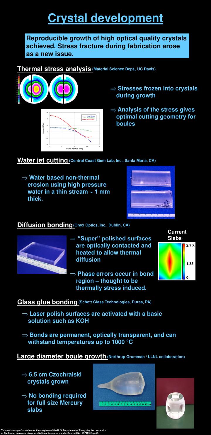
1 2 3 4 5 6 7 8 9 10 11 12 13 14 15 cm Crystal development Reproducible growth of high optical quality crystals achieved. Stress fracture during fabrication arose as a new issue. Thermal stress analysis (Material Science Dept., UC Davis) • Stresses frozen into crystals during growth • Analysis of the stress gives optimal cutting geometry for boules Water jet cutting (Central Coast Gem Lab, Inc., Santa Maria, CA) • Water based non-thermal erosion using high pressure water in a thin stream ~ 1 mm thick. Diffusion bonding (Onyx Optics, Inc., Dublin, CA) Current Slabs • “Super” polished surfaces are optically contacted and heated to allow thermal diffusion • Phase errors occur in bond region – thought to be thermally stress induced. Glass glue bonding (Schott Glass Technologies, Durea, PA) • Laser polish surfaces are activated with a basic solution such as KOH • Bonds are permanent, optically transparent, and can withstand temperatures up to 1000 °C Large diameter boule growth (Northrup Grumman / LLNL collaboration) • 6.5 cm Czochralski crystals grown • No bonding required for full size Mercury slabs This work was performed under the auspices of the U. S. Department of Energy by the University of California, Lawrence Livermore National Laboratory under Contract No. W-7405-Eng-48.
HeNe Substrate Alcohol Etchant vapo r solutio n Liqui d Alcoho l Technological advancements on the Mercury laser Phase correction Compensates for static phase distortions in S-FAP slabs, system optics, front end, as well as point operation thermal correction • Capabilities: • Maximum P-V modulation 7 microns • Minimum feature size ~ 1 mm • Plate size 30 x 30 cm2 • Plate thickness > 300 mm Far fields from amplifier alone: Without phase corrector With phase corrector 90% Energy in 5 TDL 12% Energy in 1 TDL 92% Energy in 5 TDL 39% Energy in 1 TDL Full system far fields: With phase corrector Without phase corrector Front end 98% Energy in 5 TDL 15% Energy in 1 TDL 49% Energy in 5 TDL 7% Energy in 1 TDL 83% Energy in 5 TDL 15% Energy in 1 TDL
Dark field Bright field Real time damage diagnostic A damage diagnostic algorithm allows automatic damage detection without user intervention. Dark field analysis(detects high spatial frequency damage) Background image Damage image Binary image with thresholding Damage - Background Bright field analysis(detects low spatial frequency damage) (a-f) Evolution of damage at 10 Hz and (g) the static near field (V-shaped cutouts are due to a fracture in phase plate.) Analysis routine