Download
1 / 19
200 likes | 311 Views
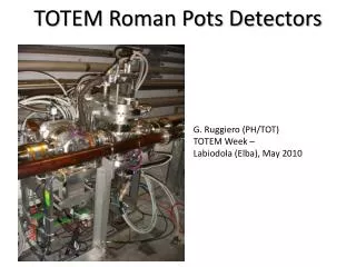
How to reduce the heating of the ALFA Roman Pots. ALFA = A bsolute L uminosity F or A TLAS. O.Berrig , F.Caspers , P.Fassnacht , S.Jakobsen , J. Kuczerowski, B.Salvant.

E N D
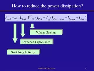
How to reduce the heating of the ALFA Roman Pots ALFA = AbsoluteLuminosityFor ATLAS O.Berrig, F.Caspers, P.Fassnacht, S.Jakobsen, J. Kuczerowski, B.Salvant
The problem with the ALFA is:Even though the POTs are in parking positioni.e. removed as much from the beam as possible (40mm)They heat up!This comes from resonances
Primer on beam impedance When a particle passes a structure, it will generate electro-magnetic fields. These electro-magnetic fields will react back on the particle itself and act as well on other particles [in the bunch itself or on following bunch(es) - if the fields have not died out before the next bunch(es) arrives] These electro-magnetic fields have two effects: A. They will give the bunch a kick Which can lead to beam instability B. They will heat up the structure Which might destroy the structure The integral of the electrical fields over the distance of the structure is voltage. The voltage divided by beam current is the beam impedance Example of destructive heating: Melting of spring that holds RF fingers http://emetral.web.cern.ch/emetral/LRFF/LRFF.htm
Primer on heating (by resonances) This is a thought experiment, where the resonator consist of basically only a capacitor. The R and L are very, very low: https://cds.cern.ch/record/1058086/files/p139.pdf It is even more a thought experiment, because the bunch induces a voltage before it reaches the resonant circuit Fig. A: The energy deposited in the resonator: I*V*dt (where dt is the length of the bunch) Fig. B: The energy deposited in the resonator for the different bunches: bunch 1: E= I*V*dtAccumulated energy: I*V*dt bunch 2: E= 2*I*V*dt Accumulated energy: 3*I*V*dt bunch 3: E= 3*I*V*dt Accumulated energy: 6*I*V*dt bunch 4: E= 4*I*V*dt Accumulated energy: 10*I*V*dt The energy which is deposited in the structure grows like a parabola. That is why resonances are so dangerous. This leads to the paradoxical statement, that in order to reduce the heat deposition, we need to add more lossy material! (when the Q of the resonator is low, the voltage has died out before the next bunch arrives)
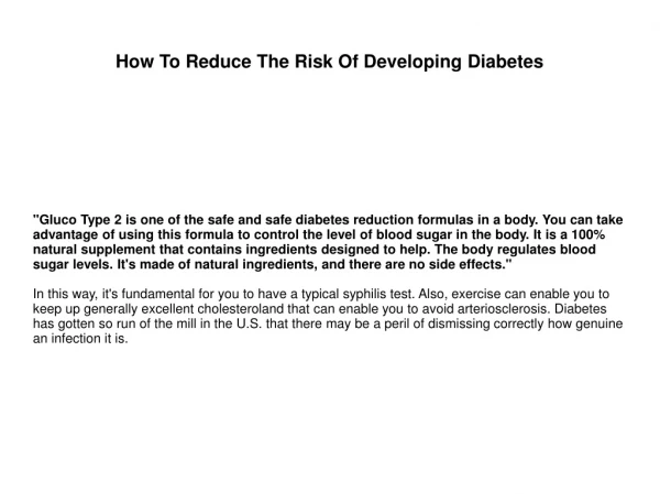
Done during specific runs, high b* values and low luminosity (few bunches) = The elastic scattering rate = Luminosity = Cross section of protons For an ideal detector, the following formula applies: http://indico.cern.ch/getFile.py/access?contribId=43&resId=1&materialId=slides&confId=14017
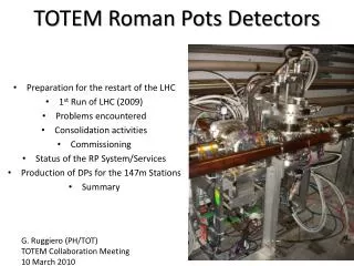
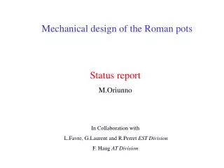
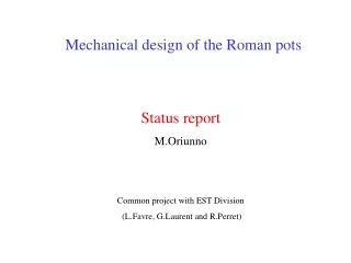
http://www.vakuum.cz/pdf_totem/M_Oriunno.pdf \\cern.ch\dfs\Users\s\SJAKOBSE\Public
Measurement setup DUT = Device under test
Measurements were done on three configurations: ALFA – Original with Roman POT filler (Designed with the help of many CST simulations by B.Salvant) ALFA - Original ALFA – Original with Station filler NB! In addition, all three configurations were tested with different ferrite options e.g.
Wire measurements in garage position [Hz] -16.6 dB comes from matching resistors [dB] In operation in 2012 Candidate to be installed in LHC in the future
In the following days (week) we might need to calculate the energy deposited in the ALFA station for the configuration with the CERN filler and with/without ring ferrites, in order to see if we can avoid the ring ferrites. [Hz] [dB] The purpose of the ring ferrites, is to remove this peak Since the ferrites are expensive; are they really necessary ? NB! 1 dB means we have lost 20% of the power at this frequency 3 dB means we have lost 50% of the power at this frequency 10 dB means we have lost 90% of the power at this frequency
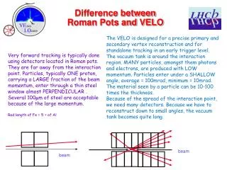
The position of the ring ferrites The ring ferrites absorb the fields that propagate along the filler to the bottom of the POT.
Measurements vs. SimulationsALFA - no roman pot filler – no ferrites Measurement for garage position(40 mm) The simulations are done with wire inserted, but without matching resistors!
Measurements vs. SimulationsALFA with roman pot filler – no ferrites Measurement for garage position(40 mm) Do we need to simulate higher frequencies? The simulations are done with wire inserted, but without matching resistors!
Conclusion The current Roman pots should not be left as they were before LS1. In order to reduce the heating of the ALFA station, two modifications were tested: “STATION FILLER” and “ROMAN POT FILLER”. The test measurements showed that the two modifications were similar in their ability to reduce the heating. The “ROMAN POT FILLER” is preferred as it is more mechanically robust.The “ROMAN POT FILLER” upgrade proposal clearly goes in the right direction if we believe simulations and bench measurements (as reviewed at LTEX of July 11th 2013 and impedance meeting of August 2nd 2013 in particular). With the information and results at our disposal, the impedance team would recommend to install the Roman pot filler and the ring ferrites. https://edms.cern.ch/comment/1288051/0.2
FUTURE DEVELOPMENTS Measurements will be done with short SUCOBOXes and attenuators in the future. (For compatibility reasons, all the ALFA measurements were done with 50mm SUCOBOXes and no attenuators) [Hz] [Hz] [dB] [dB] The above measurements were done on the ALFA reference chamber Frequency interval corresponds to twice the length of the REFERENCE CHAMBER + length of the two SUCOBOXES*. Δf = c/((LREFERENCE CHAMBER + 2*LSUCOBOX)*2) Δf = c/((0.420+ 2*0.035)*2) Δf = 0.306 GHz * It is probaly more the length between the end of the REFERENCE CHAMBER and where the reflection happens in the resistor.
FUTURE DEVELOPMENTS Replace the matching resistor with a small printed circuit and SMD type resistor. This should improve matching over a larger frequency range. The standing wave along the length of the DUT, would then disappear. Also some way should be found to replace the soldering!
FUTURE DEVELOPMENTS Replacing ferrites with loops. Proof of principle The measurement was done at the position, which is closest to the beam that we can measurei.e. 3mm. We managed to reduce the resonance at 1.08 GHz, however we created a new resonance at 0.948 GHz. The resonance at 1.97 GHz was suppressed, but a new resonance at 1.87 GHz was created. The huge resonance at 2.31 GHz was reduced by 10 dB. However, the remaining resonance is wider than the original. One loop