Download
1 / 39
390 likes | 504 Views
CS352 Review Session. TA: Behnam Robatmili. Jargons. 1 Byte = 8 bits 1 Word = 4 Bytes Frequent used numbers 8 = 2 3 , 16(4), 32(5), 64(6), 128(7), 256(8) 1 K = 2 10 , 1M = 2 20 , 1G = 2 30. Chapter 2: Instructions. Assembly instructions Vs Machine instructions Assembly: add $t0, $s2, $t0

E N D
CS352 Review Session TA: Behnam Robatmili
Jargons • 1 Byte = 8 bits • 1 Word = 4 Bytes • Frequent used numbers • 8 = 23, 16(4), 32(5), 64(6), 128(7), 256(8) • 1 K = 210, 1M = 220, 1G = 230
Chapter 2: Instructions • Assembly instructions Vs Machine instructions • Assembly: add $t0, $s2, $t0 • Machine: 000000 10010 00100 00100 00000 100000 op rs rt rd shamt funct • Conversion done by Assembler
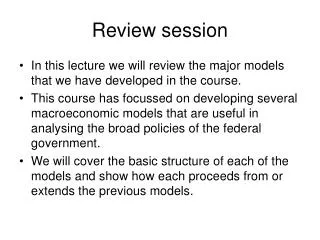
Application (Netscape) Operating Software Compiler System (Linux) Assembler Instruction Set Architecture Processor Memory I/O system Hardware Datapath & Control Digital Design Circuit Design transistors Performance Design Abstractions • Coordination of many levels of abstraction SpeedPowerSize
Chapter 2 Cont’d • Most instructions only access registers in CPU (e.g., R-type, J-type) • Two instructions to access memory (lw/sw) ALU Register File (S0, S1…) Memory (Instruction, Data)
Chapter 2 Cont’d • Understand frequently used instructions • Arithmetical: add/sub • Logical: and/or • Shift: sll/srl • Comparison: slt • Branch: beq/bne/j • Access memory: lw/sw • Write small programs in assembly codes (see hw 2.8, 2.10, 2.34)
The $0 register becomes useful again for the beq Review: slti example • C code fragment if (i < 20) { f=g+h; } else { f=g-h; } • re-written C code temp = (i < 20)? 1 : 0; if (temp == 0) goto L1; f=g+h; goto L2; L1: f=g-h; L2: • MIPS code slti $t1,$s3,20 beq $t1,$0,L1 add $s0,$s1,$s2 j L2 L1: sub $s0,$s1,$s2 L2:
C functions main() { int i, j, k, m; i = mult(j,k); ... ; m = mult(i,i); ... } int mult (int x, int y) { int f; for (f= 0; y > 0; y- - ) { f += x;}return f; } • Functions, procedures one of main ways to give a program structure, and encourage reuse of code. • But they do not add any more computational power. What information mustcompiler/programmer keep track of?
Calling functions: Bookkeeping • Function address • Return address • Arguments • Return value • Local variables • Most problems above are solved simply by using register conventions. Labels $ra (same as $31) $a0, $a1, $a2, $a3 $v0, $v1 $s0, $s1, …, $s7
Calling functions: example … c=sum(a,b); … /* a,b,c:$s0,$s1,$s2 */}int sum(int x, int y) { return x+y;} address1000 add $a0,$s0,$0# x = a1004 add $a1,$s1,$0# y = b1008 addi $ra,$0,1016# $ra=10161012 j sum# jump to sum1016 add $s2,$0,$v0# c=$v0 ... 2000 sum: add $v0,$a0,$a1# x+y2004 jr $ra # pc = $ra = 1016 Why jr $ra vs. j 1016 to return?
Calling functions: jal, jump and link • Single instruction to jump and save return address: jump and link (jal) • slow way: 1008 addi $ra,$zero,1016#$ra=1016 1012 j sum#go to sum • faster way and save one instruction: 1012 jal sum# pc = $ra = 1016 • but adds more complexity to the hardware • Why have a jal? Make the common case fast: functions are very common.
Calling functions: setting the return address • Syntax for jal (jump and link) is same as for j (jump): jal label# reg[$ra]=pc+4; pc=label • jal should really be called lajfor “link and jump”: • Step 1 (link): Save address of next instruction into $ra (Why?) • Step 2 (jump):Jump to the given label
Calling functions: return • Syntax for jr (jump register): jr $register# reg[$pc] = $register • Instead of providing a label to jump to,the jr instruction provides a register that contains an address to jump to. • Usually used in conjunction with jal,to jump back to the address thatjal stored in $ra before function call.
Calling nested functions: example int sumSquare(int x, int y) { return mult(x, x)+ y;} • Something called sumSquare, now sumSquare iscallingmult(x, x). • So there’s a value in $ra that sumSquare wants to jump back to, • but this will be overwritten by the call to mult. • Need to save sumSquare return address before call to mult(x, x).
Calling nested functions: memory areas • In general, may need to save some other info in addition to $ra. • When a C program is run, there are 3 important memory areas allocated: • Static: Variables declared once per program, cease to exist only after execution completes • Heap: Variables declared dynamically • Stack: Space to be used by procedure during execution; this is where we can save register values • Not identical to the “stack” data structure!
Space for saved procedure information $sp stack pointer Explicitly created space, e.g., malloc(); C pointers Variables declared once per program(.data segment) Code Static Heap Stack Program(.text segment) C memory Allocation Address ¥ 0
Coding • Make sure to check programs in pp#83, #84 • Pointers to improve performance • Procedure calls • Place params $a0-2 • Transfer controls $jal • Acquire storage $sp, $fp and set new $fp • Run Proc • Place the results $v0-1 • Return $ra
Sample Function • calc_fact: # based on the "fact" function in the text • sub $sp, $sp, 12 • sw $a0, 8($sp) # first item on stack: n • sw $ra, 4($sp) # secnd item on stack: return addr • sw $fp, 0($sp) # third item on stack: fp • slt $t0, $a0, 2 # if n < 2, n! = 1 • beq $t0, $zero, L1 # if n > = 1 ,go to L1 • addi $v0, $zero, 1 # return 1 • addi $sp, $sp, 12 # pop stack • jr $ra • ….
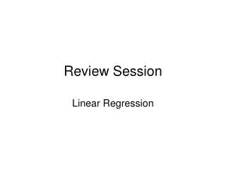
Chapter 3: Arithmetic • Two’s complement • What’s the range 4 bits can represent? • Addition & Subtraction • Floating Points • (-1)S * (1 + Fraction) * 2(Exponent-Bias) • Single: Fraction/23, Exponent/8, Bias 127 • Double: Fraction/52, Exponent/11, Bias 1023 • Adder Design (hw 3, part 2)
Floating Point Numbers Ranges: D-norm number ±[2-149(1-2-23)*2-126] Norm number ±[2-126(2-2-23)*2127]
Carry Skip Adder Tcarry = (k-1)tr+(n/k-2)(ts+tb)+(k-1)tr Tcarry = (2k+n/k-4)2Δg For k = √(n/2) for MIPS 32 Topt = 24Δg
Chapter 4: Performance • Performance can only be compared by time • Speedup = Timeold/Timenew • Time = IC * CPI * Cycle Time • Avg CPI = Σ (CPIx * Frequencyx)
Chapter 5: Datapath & Control • Control Signals • MemWrite/MemRead • PCWrite • RegWrite • Mux selector • IorD • MemtoReg • PCSource • RegDst
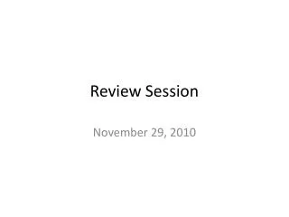
I n s t r u c t i o n R-format datapath control (Figures 5.20-24) Machine Memto Reg Mem Memopcode RegDstALUSrcReg WriteReadWriteBranch ALUopR-format 1 ($rd) 0 ($rt) 0(alu) 1 0 0 0 10 (func) PCSrc M A d d u x Add Result 4 RegWrite S h i f t l e f t 2 MemWrite MemRead RegDst ALUctl 3 R e a d ALUSrc MemtoReg R e a d r e g i s t e r 1 P C R e a d a d d r e s s R e a d d a t a 1 Z e r o r e g i s t e r 2 A L U A L U R e a d W r i t e R e a d M A d d r e s s r e s u l t M u d a t a r e g i s t e r d a t a 2 M u I n s t r u c t i o n x u x W r i t e m e m o r y D a t a x d a t a m e m o r y W r i t e d a t a 3 2 1 6 S i g n e x t e n d
I n s t r u c t i o n lw datapath control (Figure 5.25) Machine Memto Reg Mem Memopcode RegDstALUSrcReg WriteReadWriteBranch ALUop lw 0 ($rt) 1 (offset)1(mem) 1 1 0 0 01 (add) PCSrc M A d d u x Add Result 4 RegWrite S h i f t l e f t 2 MemWrite MemRead RegDst ALUctl 3 R e a d ALUSrc MemtoReg R e a d r e g i s t e r 1 P C R e a d a d d r e s s R e a d d a t a 1 Z e r o r e g i s t e r 2 A L U A L U R e a d W r i t e R e a d M A d d r e s s r e s u l t M u d a t a r e g i s t e r d a t a 2 M u I n s t r u c t i o n x u x W r i t e m e m o r y D a t a x d a t a m e m o r y W r i t e d a t a 3 2 1 6 S i g n e x t e n d
I n s t r u c t i o n sw datapath control Machine Memto Reg Mem Memopcode RegDstALUSrcReg WriteReadWriteBranch ALUop swX 1 (offset) X 0 0 1 0 01 (add) PCSrc M A d d u x Add Result 4 RegWrite S h i f t l e f t 2 MemWrite MemRead RegDst ALUctl 3 R e a d ALUSrc MemtoReg R e a d r e g i s t e r 1 P C R e a d a d d r e s s R e a d d a t a 1 Z e r o r e g i s t e r 2 A L U A L U R e a d W r i t e R e a d M A d d r e s s r e s u l t M u d a t a r e g i s t e r d a t a 2 M u I n s t r u c t i o n x u x W r i t e m e m o r y D a t a x d a t a m e m o r y W r i t e d a t a 3 2 1 6 S i g n e x t e n d
I n s t r u c t i o n beq datapath control (Figure 5.26) Machine Memto Reg Mem Memopcode RegDstALUSrcReg WriteReadWriteBranch ALUop beq X 0 X 0 0 0 1 01 (sub) And M A d d u x Add Result 4 Branch RegWrite S h i f t l e f t 2 MemWrite MemRead RegDst ALUctl 3 R e a d ALUSrc MemtoReg R e a d r e g i s t e r 1 P C R e a d a d d r e s s R e a d d a t a 1 Z e r o r e g i s t e r 2 A L U A L U R e a d W r i t e R e a d M A d d r e s s r e s u l t M u d a t a r e g i s t e r d a t a 2 M u I n s t r u c t i o n x u x W r i t e m e m o r y D a t a x d a t a m e m o r y W r i t e d a t a 3 2 1 6 S i g n e x t e n d
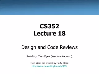
Single Cycle Datapath Adder2: PCPC+signext(IR[15-0]) <<2 Adder3: Arithmetic ALU Adder1: PC PC + 4 • Eachinstruction executes in a single cycle• Every instruction and clock-cycle must be stretched to accommodate the slowest instruction (p.438) Single Cycle = 2 adders + 1 ALU + 4 muxes
Chapter 5 Cont’d • Multicycle Implementation (pp325-329) • IF -> ID -> EX -> MEM -> WB • Some instructions do nothing in certain steps Consider R-type in MEM step • Cycle time is determined by the slowest step
Multi-cycle: 5 execution steps • T1 (a,lw,sw,beq,j) Instruction Fetch • T2 (a,lw,sw,beq,j) Instruction Decode and Register Fetch • T3 (a,lw,sw,beq,j) Execution, Memory Address Calculation, or Branch Completion • T4 (a,lw,sw) Memory Access or R-type instruction completion • T5 (a,lw) Write-back step INSTRUCTIONS TAKE FROM 3 - 5 CYCLES!
Multi-cycle Approach All operations in each clock cycle Ti are done in parallel not sequential! For example, T1, IR = Memory[PC] and PC=PC+4 are done simultaneously! T1 T2 T3 T4 T5 Between Clock T2 and T3 the microcode sequencer will do a dispatch 1