Download
1 / 33
340 likes | 560 Views
Vanderbilt University Rocket Launched Reconnaissance UAV. Flight Readiness Review. Team Roster. Advisors Professor Dr. A.V. Anilkumar Safety Officer Robin Midgett Rocket Technical Advisors Rodney McMillan (NAR II, LEU/D) Russell Bruner (NAR III) UAV Technical Advisors

E N D
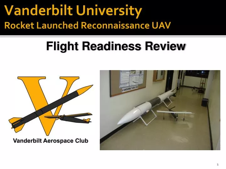
Vanderbilt University Rocket Launched Reconnaissance UAV Flight Readiness Review
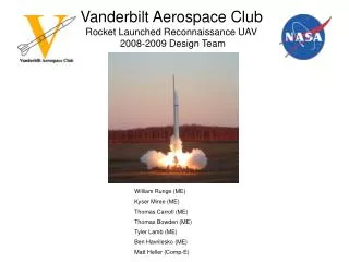
Team Roster • Advisors • Professor Dr. A.V. Anilkumar • Safety Officer Robin Midgett • Rocket Technical Advisors • Rodney McMillan (NAR II, LEU/D) • Russell Bruner (NAR III) • UAV Technical Advisors • Charles Waterston (Music City Aviators R/C Club, President) • Randy Moore (Test Pilot) • Students William Runge Kyser Miree Thomas Bowden Tyler Lamb Ben Havrilesko Matt Heller Thomas Carroll Ty Barringer Ryan Taylor Zach Smith Erin McManus Ben Chociej HaziqMazlan
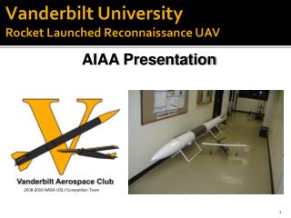
Mission Statement • The goal of the 2009 Vanderbilt University Student Launch Initiative is to design, build, test, and successfully launch a rocket-deployed reconnaissance UAV. • The UAV must be flown from a computer terminal to an area of interest and collect high resolution images as well as thermal data. • The project is motivated in part by the DARPA RapidEye project, which seeks to deploy a reconnaissance UAV from an InterContinental Ballistic Missile (ICBM) for rapid-deployment reconnaissance in the visual and infrared spectra.
Project Summary • A 16’-tall, 10”-diameter rocket carries a small UAV to altitude • At altitude, the UAV is deployed from the rocket, packaged inside a protective foam sabot • Once deployed, the UAV is controlled by two operators at a pair of ground station computers • Pilot flies and navigates the aircraft by monitoring a graphic user interface which provides data from a wide array of sensors onboard the UAV. • Payload specialist operates a high-resolution camera and infrared thermometer on a tilt-pan gimbal. • After conducting a reconnaissance mission, the UAV is navigated back to the ground station, where it is landed visually.
Rocket Summary • Based on the 10” Thumper Kit from Polecat Aerospace • 10” in diameter, 16’-tall • In-house carbon-fiber fins have replaced the plywood fins supplied with the kit to save weight. • 8’-tall payload section will house the UAV • Specialized triple deployment scheme facilitates safe deployment of UAV and parachutes • Payload tube elongated since CDR to permit larger UAV wingspan
Payload Integration • The UAV will be packaged inside the payload tube • A foam sabot will protect the UAV during launch and deployment • Black powder charges will eject the sabot, which will then fall away to release the UAV • Folding propeller and control surfaces allow the UAV to be packaged inside the sabot
Rocket Stability Diagram • CP: 157.0” from nose • CG: 129.8” from nose • Stability Margin: 2.72 calibers • Thrust to Weight Ratio: 3.38 (M1939W)
Rocket Thrust Simulation • Motor: Aerotech M1939W • Thrust: 10339.8 N-sec Total Impulse • Average: 1477 N • Total Rocket Weight: 63 lb, without motor • Rail Exit Velocity: 60 ft/s (Rocksim, 16’-rail) Rocket Flight Simulation Motor Thrust Curve
Parachute Sizes and Descent Rate * The weight of the payload section decreases by 6.5 lbs when the UAV is deployed. ** This calculation neglects drag on the body/fins/nose of the rocket. Actual descent rates can be expected to be somewhat slower.
Rocket Altimeter Testing • A vacuum chamber was built, sized to contain all 4 of the rocket’s altimeters at once. • A vacuum pump pulls out air to simulate the rocket’s flight to altitude • Based on comparing the vacuum pressure read out from the vacuum gauge to the altitude reported by the altimeters • All altimeters have been shown to be accurate and functional.
Deployment Charge Testing • Redundant altimeters and charges for each deployment. • Charges sized per Canepa [2]. • Black powder charge sizes experimentally verified via ground deployment testing. • Verified during March 15 full scale test launch
Fin Strength Testing • Carbon-fiber fins (3 layers of 15.6 oz CF) have been fabricated in-house to save weight on the rocket, replacing plywood fins supplied with the rocket kit. • A tensile strength test was performed • A comparison of the tensile strength of carbon fiber fins to the kit-supplied plywood fins has demonstrated that the CF fins are sufficiently strong for flight. • Average CF sample strength of ~5,000 lbs was considerably larger than that of the plywood sample
Rocket Flight Testing • A full-scale test launch was performed on March 15 • Competition rocket flew a M1297W to an altitude of 1871 ft (RockSim predicted 2000ft) • UAV was deployed at 700’ and flown visually
Rocket was successfully launched after ~2 hours of preparation • UAV was packaged inside Rocket • UAV was successfully deployed clear of the rocket via the Sabot • UAV wing rotated, V-Tails folded forward, and the aircraft was flown for ~8 minutes • Tail Section main parachute deployed prematurely due to excessively large drogue parachute leading to shear pin failure • Sabot was fractured in deployment; needs to be reinforced
Rocket Verification Plan 1. RockSim design work COMPLETE 2. Parachute sizing, deployment charge sizing COMPLETE 3. Ground testing– altimeter testing, deployment testing, fin material load testing COMPLETE 4. Full scale flight test (March 15th) COMPLETE
Payload Summary: Reconnaissance UAV • Completely designed and built in house from scratch • Onboard flight computer • Sophisticated sensory array • Rotating wing (58” span) • Folding Propeller • Folding V-Tail • 8.5 lb overall weight • Piloted remotely from a pair of computers
Wind Tunnel Testing • Exact 1/6th scale model of UAV has been fabricated using a Rapid Prototyping Machine • Model has been coated with body filler to form smooth surfaces • Model has been assembled and fitted to the Sting in the wind tunnel • Wind Tunnel testing is underway • Testing will establish: • Loss of lift resulting from fuselage interference with wing • Drag resulting from fuselage, V-tails, interference, etc.
Flight Testing • Second iteration of UAV has been extensively flight tested • logged 25 minutes of flight time total • 3 separate flights from the ground • successfully deployed from the rocket, safely flown and landed
Flight Testing (continued) • Minor stability problems related to CG placement • More lift necessary for UAV electronics • Corrected on competition UAV design • Nose extended by 4 inches • Wingspan increased by 10 inches • Continual improvement of fabrication techniques • Various weight-reduction modifications undertaken • Design optimizations will take the form of the Competition UAV; 2nd Proof of Concept UAV will serve as backup.
UAV ElectronicsSummary Page • A 500 MHz single-board computer is the heart of the flight computer • Digital devices/sensors, such as the GPS, and IR thermometer interface directly to the single board computer (SBC) via USB or serial. • Micro-controllers are used to collect and process the information from an array of analog sensors and to generate pulse-width modulation signals for controlling servos • Surveillance Package • Forward facing camera • Downward facing, high-resolution camera coupled with infrared thermometer
UAV Electronics Single-Board Computer and Related Subsystems • Single-Board Computer • Surveillance camera • Infrared thermometer • GPS receiver • Interfaces to microcontrollers • In house custom circuitry • Linear accelerometer (3 axes) • Angle roll-rate sensor (3 axes) • Altimeter • Pitot-static • PWM output for servos • Multiplexer for standby/WiFi switching
Electronics Testing • 8’ wingspan Telemaster was flown with forward facing camera, GPS, and on-board computer • WiFi has been tested for short range reliability • PWM controller has been controlled by the SBC via WiFi signal from ground station hardware • Ground Station antenna array is assembled and has been tested for functionality
Ground Station Schematic Ground Station Consists of: • Wifi dish and uplink to UAV • Analog Receivers for video feed from NAVCAM and R-CAM • Pilot’s station: laptop and flight controller • Payload Specialist’s station: laptop and camera controller • Path Loss Calculations • Wifi range: 10 miles • NAVCAM range: 9 miles • R-CAM range: 7 miles • Standby GPS Range: 20 miles
Standby Systems and Safety AssuranceSummary Page • No single system failure can lead to the aircraft being lost. • Pilot, flying by reference to the ground station computer terminals, is assisted by a copilot, observing the UAV visually. • In the event that the pilot endangers the aircraft, the Copilot can assume control at any time • Either pilot can deploy the Ballistic Recovery System Parachute at any time • Co-Pilot is an experienced R/C pilot who also landed the plane visually after the Test Launch on 3-15-09. • Successful flight test launch demonstrated concept of Rocket-Launched UAV, with wing rotation, V-tails locking into place, and landing gear being successfully deployed. • Flight testing at Peeler park has proven the flightworthiness of all aircraft built by the Vanderbilt USLI Team • Further flight testing will demonstrate the concept of flight solely by reference to computer.
Fabrication Technique Improvements • Use of fiberglass screws, aluminum bolts, aluminum hinges • Significant weight reduction • Balsa caps where hinges connect to control surfaces • Improved reliability of control surfaces • Internal mounting improvements • Ruggedness, secure CG
Fabrication Technique Improvements (continued) • “Honeycomb” cutout pattern on wing foam • Will reduce wing weight • Rubber bands to replace springs • Contribute to weight reduction without loss of strength or reliability • Lost foam method • Blue foam molds can be used to lay composites, then dissolved using acetone • ProMechanica is used to identify areas of small loading, to reduce weight, and large loading, to increase strength. • Interior hinge placement for reduced drag • Balsa spar to ensure proper dihedral and increase wing strength.
UAV Verification Plan 1. First Proof of Concept UAV…………………………………………………………………………………………………………….COMPLETE Demonstrates design and fabrication methodology 2. Analytical Design Work……………………………………………………………………………………………………....….…………..COMPLETE Fluent, ProMechanica, Profili 3. Computer Aided Design……………………………………………………………………………………………………………………COMPLETE ProEngineer . 4. Second Proof of Concept UAV……………………………………………......................................................................…….COMPLETE Demonstrates deployment from Rocket Serves as a backup to the Competition UAV 5. Experimental Model Studies……………………………………………………………………………………………………...…..UNDERWAY Wind Tunnel Testing 6. Ground-Test the Electronics suite and camera systems……………………………….…………..UNDERWAY 7. Flight-Test the Electronics suite and camera systems…………………………………………..……UNDERWAY 8. Competition UAV…………………………………………………………………………………………………………………………….……..UNDERWAY Refined version of 2nd Proof of Concept. Reduced weight, various Design enhancements, increased wingspan. 9. Flight test UAV with full payload Electronics……………………………………………………………….…….PENDING 10. Flight Test Full System……………………………............……………………………………………………………...………..…….PENDING
Outreach Plan The team’s outreach will take place in 3 phases, with 3 target audiences. • Adventure Science Center (COMPLETED) • Displayed rocket and UAV • Provided Realflight G3.5 R/C Flight Simulator for kids to learn to fly R/C airplanes • Exposure of over 300 elementary school, middle school, and high school students • Boy Scouts and Girl Scouts of America (COMPLETED) • Gave talk in auditorium on campus • Demonstrated a static rocket flight with motor burn and parachute deployment on a small rocket. • Provided display of Proof of Concept aircraft, Telemaster, Competition rocket, etc. • Exposure of at least 30-40 scouts • Hillsboro High School Science Class • Will display the Rocket and Competition UAV • Will meet with several different science classes • Will give a brief PowerPoint presentation on the design • Expected exposure of about 60 students
Conclusion • Rocket Progress • Essentially complete • Small modifications will be made to shear pins, sabot • Proven as reliable launch vehicle • UAV Progress • First Proof of Concept UAV designed, analyzed, fabricated, and tested • Second Proof of Concept UAV designed, analyzed, fabricated, and tested • Competition UAV designed, analyzed, fabrication underway • UAV Electronics Suite • Design complete, assembly underway • Ground and flight testing underway
Works Cited • Anderson Jr., John D. Introduction to Flight. 6th Edition. New York: McGraw-Hill, 2008. • Canepa, Mark. Modern High-Power Rocketry 2. Victoria: Trafford Publishing, 2005. • Hiller, Jordan. "Model Rocket Parachute Descent Rate Calculator." OnlineTesting.net - Online Quiz and Testing Solutions. 19 Jan. 2009 <http://www.onlinetesting.net/cgi-bin/descent3.3.cgi>. • Hobby Lobby's RC Catalog” AXI Motor Selector Tool. 20 Jan. 2009 <http://www.modelmotors.cz/axisetuphobby-lobby/>. • Lennon, Andy. The Basics of R/C Model Aircraft Design. Air Age Media Inc.: Ridgefield, CT. 1996. • Raymer, Daniel P. Aircraft Design: A Conceptual Approach. 4th Edition. Reston: American Institute of Aeronautics and Astronautics, Inc., 2006. • Raymer, Daniel P. Simplified Aircraft design for homebuilders. Los Angeles: Design Dimension Press, 2003. • Runge, William. "Characterizing the Aerodynamics of a UAV Wing." 18 Dec. 2008. Vanderbilt University, Nashville, TN. 19 Jan. 2009 <http://www.vanderbilt.edu/USLI/gallery/inthelab/fluent/UAV_Wing_Aerodynamics.pdf>.