Download
1 / 45
3.57k likes | 10k Views
TACHEOMETRIC SURVEYING. CONTENTS. Tacheometric Surveying Tangential, Stadia and sub-tense methods Stadia Systems Horizontal and inclined sights Vertical and Normal Staffing Fixed and movable hairs Stadia constants Anallactic lens Subtense bar. Introduction.

E N D
CONTENTS Tacheometric Surveying Tangential, Stadia and sub-tense methods Stadia Systems Horizontal and inclined sights Vertical and Normal Staffing Fixed and movable hairs Stadia constants Anallactic lens Subtense bar Sivapriya Vijayasimhan
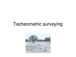
Introduction Tacheometry – Greek word means quick measure Measuring horizontal and vertical distance of a points on the earth surface relatively to one another are determined without using a chain or tape or a separate levelling instrument. Preparation of contoured maps or plans with higher accuracy and also, it provides a check on distances measured with the tape. Need of Tacheometry : steep and broken ground, deep revines, stretches of water or swamp etc., where chaining is difficult or impossible Sivapriya Vijayasimhan
Uses of Tacheometry Measuring horizontal distances and differences in elevations. Preparation of topographic maps which require both elevations and horizontal distances Survey work in difficult terrain where direct methods are inconvenient Detail filling Reconnaissance surveys for highways, railways, etc. Checking of already measured distances Hydrographic surveys Establishing secondary control Sivapriya Vijayasimhan
Instrument • Transit theodolite fitted with a stadia diaphragm • In addition to it, convex lens (anallatic lens)is provided between the eye-piece and the object glass at a fixed distance. Various pattern of stadia diaphragm • Levelling Staff • Stadia Rod Sivapriya Vijayasimhan
Instrument • Transit theodolite fitted with a stadia diaphragm • The stadia diaphragm essentially consists of one stadia hair above and the other an equal distance below the horizontal cross-hair, the stadia hairs being mounted in the ring and on the same vertical plane as the horizontal and vertical cross-hairs. • (1) The simple external-focusing telescope • (2) The external-focusing anallactic telescope (Possor`s telescope) • (3) The internal-focusing telescope. Sivapriya Vijayasimhan
Tangential System Diaphragm of the tacheometer is not provided with stadia hair Single Horizontal Hair is used Staff consist of two vanes at known distances Two points are required to measure staff intercept Angles, elevations or depressions are measured Tangents are used to measure horizontal distances and elevations (not generally used) Sivapriya Vijayasimhan
Stadia System Principle: Tacheometric angle is constant Staff intercept varies with distance between staff and instruments, which forms base Diaphragm of tacheometer is provided with two stadia hair (upper and lower) Telescope is directed towards the staff held at a point whose distance from instruments is to be found Difference in these readings gives staff intercept Horizontal distance is obtained by multiplying staff intercept bymultiplying constant Two Methods 1.Fixed hair 2.Movable Hair Method Sivapriya Vijayasimhan
Subtense Method Reverse of stadia method 2. Staff intercept forms fixed base 3. Tacheometric angle according with staff position Fixed Base : fixed distance between two tangents or vanes Interval between the stadia wires is changed till lines of sight coincide with tangents and the subtended angle is noted Base may be vertical or Horizontal Base Vertical : Movable Hair method or Vertical base subtense method Vertical angle is measured with the help of special diaphragm – high accuracy Base Horizontal :Horizontal base subtense method Horizontal angle is measured by method of repetition using Transient theodolite example: Subtense bar method Sivapriya Vijayasimhan
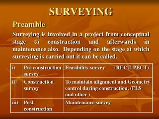
S3 S1 S2 A O’ B’ β i A’ D1 B D2 D3 O Q R P Sivapriya Vijayasimhan Principle of Tacheometer Based on Isoscales Triangle Ratio of k = ½ cot β/2 f – focal length i- stadia intercept
Sivapriya Vijayasimhan Tacheometer must essentially incorporate the following features: • The multiplying constant should have a nominal value of 100 and the error contained in this value should not exceed 1 in 1000. • The axial horizontal line should be exactly midway between the other two lines. • The telescope should be truly anallactic. • The telescope should be powerful having a magnification of 20 to 30 diameters. • The aperture of the objective should be 35 to 45 mm in diameter to have a sufficiently bright image. • For small distances (say upto 100 meters), ordinary levelling staff may be used. For greater distances a stadia rod may be used. • A stadia rod is usually of one piece, having 3 – 5 meters length. • A stadia rod graduated in 5 mm (i.e. 0.005 m) for smaller distances and while for longer distances, the rod may be graduated in 1 cm (i.e. 0.01 m).
10' 7" Common Patterns of Stadia Rods LC of the stadia rods are less than the LC of ordinary Levelling Staff
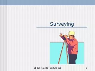
A Object glass O B’ C’ A’ S i F V C }} f d B v u A, B, and C -the points cut by the three lines of sight corresponding to three wires A’, B’ and C’ - top, bottom and axial hairs of the diaphragm i= interval b/w the stadia hairs (stadia interval) – length of image AB = S = staff intercept F= focus f = focal length of the objective V = vertical axis of the instrument v=distance between optical centre and image u= distance between optical centre and staff d= distance between optical centre and vertical axis of instrument Stadia Tacheometry Sivapriya Vijayasimhan
Similar triangle B’O’A’ and BO’A i/S = v/u v = iu/S Properties of Lens , 1/v + 1/u = 1/f Sub values of v, 1/(iu/S) + 1/u = 1/f S/iu + i/u = 1/f 1S + 1 = 1 u i f u = S + 1 f i D = u + d = S + 1 f + d i D = (f/i) x S + (f+d) f/i – multiplying : f+d – additive constant Sivapriya Vijayasimhan
O is the optical centre of the objective of an external focusing telescope A, B and C = the points cut by the three lines of sight corresponding to three wires a, b and c = bottom, top and hairs of the diaphragm ab = i = interval b/w the stadia hairs (stadia interval) AB = s = staff intercept; f = focal length of the objective Sivapriya Vijayasimhan Horizontal Sight A, C, and B = the points cut by the three
f1 s f2i f1 s f2 i = = 1 1 1 f f1 f2 = + f i D = s + (f + d) = k . s + C f1 = horizontal distance of the staff from the optical centre of the objective f2 = horizontal distance of the cross-wires from O. d = distance of the vertical axis of the instrument from O. D = horizontal distance of the staff from the vertical axis of the instruments. M = centre of the instrument, corresponding to the vertical axis. Since the rays BOb and AOa pass through the optical centre, they are straight so that AOB and aOb are similar. Hence, Again, since f1 and f2 are conjugate focal distances, we have from lens formula, f1 f2 Multiplying throughout by ff1, we get f1 = f + f Substituting the values of in the above, we get s i f1 = f + f Horizontal distance between the axis and the staff is D = f1 + d
1 1 1 f f1 f2 = + Equation is known as the distance equation. In order to get the horizontal distance, therefore, the staff intercept s is to be found by subtracting the staff readings corresponding to the top and bottom stadia hairs. • Determination of constant K and C • 1stmethod: • In this method, the additive constant C = (f + d) is measured from the instrument while the multiplying constant k is computed from field observations: • Focus the instrument to a distant object and measure along the telescope the distance between the objective and cross-hairs, • The distance d between the instrument axis and the objective is variable in the case of external focusing telescope, being greater for short sights and smaller for long sights. It should, therefore be measured for average sight. Thus, the additive constant (f + d) is known.
D1 – C s 3. To calculate the multiplying constant k, measure a known distance D1 and take the intercept s1 on the staff kept at that point, the line of sight being horizontal. Using the equation, D1 = ks1 + C or k = For average value, staff intercepts, s2, s3 etc., can be measured corresponding to distance D2, D3 etc., and mean value can be calculated. Note:In case ofsome external focusing instruments, the eye-piece-diaphragm unit moves during focusing. For such instruments d is constant and does not vary while focusing. • 2nd method: • In this method, both the constants are determined by field observations as under: • Measure a line, about 200m long, on fairly level ground and drive pegs at some interval, say 50 meters. • Keep the staff on the pegs and observe the corresponding staff intercepts with horizontal sight. • Knowing the values of D and s for different points, a number of simultaneous equations can be formed by substituting the values of D and s in equation D = k.s + C. The simultaneous solution of successive pairs will give the values of k and C, and the average of these can be found.
For example, if s1 is the staff intercept corresponding to distance D1 and s2 corresponding to D2 we have, D1 = k.s1 + C . . . . . (i) and D2 = k. s2 + C . . . . . (ii) Subtracting (i) from (ii), we get D2 – D1 s2 – s1 k = . . . . . . . . . (1) Substituting the values of k in (i), we get D2 – D1 s2 – s1 C = D1 - s1 D1s2 – D2s1 s2 – s1 . . . . . . . . . (2) = Thus equation (1) and (2) give the values of k and C.
FIXED HAIR METHOD OF STADIA SYSTEM • Distance between the stadia hair is fixed • Distance between the station and staff = staff intercept x stadia constants Methods to find Stadia Constants 1. Line of sight is horizontal and staff vertical 2. Line of sight inclined upwards and staff vertical 3. Line of Sight inclined upwards and staff normal 4. Line of Sight inclined downwards with staff vertical 5. Line of sight inclined downwards and staff normal Sivapriya Vijayasimhan
S O’ Height of Instrument (Hi) h BS P O BM D Line of Sight Horizontal and Staff Vertical General Tacheometric equation : =100 & = 0 RL of Staff station, P = Hi – h Where as Hi = RL of BM + BS BS = Back Sight h = central hair reading Sivapriya Vijayasimhan
A A` B L h C C` α V P O’ Ө P’ O D 2.Line of sight inclined upwards and staff vertical S α Line of axis
Ois the optical centre of the objective of an external focusing telescope A, B and C = the positions of staff corresponding to the cut points of the stadia and central hairs S= AC = staff intercept h=central hair reading V=vertical distance between instrument axis central hair D=horizontal distance between instrument and staff L=inclined distance between instrument axis and B θ = angle of elevation α = angle made by outer and inner rays with central ray A’C’ is drawn perpendicular to central ray, O’B L = + Consider triangle ABA’ and CBC’ ABA’ = CBC’ = AA’B = 90o + α BC’C = 90o –α hence α is very small, it is taken as zero Sivapriya Vijayasimhan
AA’B and BC’C = 900 So, AC’ = AC cos = S cos Then x + Sivapriya Vijayasimhan
A A` B L h C C` α V P O’ Ө P’ O D 3.Line of sight inclined upwards and staff normal S h cos θ α Line of axis h sin θ L cos θ
RL of staff station, P = (RL of instrument axis) +V – h cos Sivapriya Vijayasimhan Vertical height of central hair = h cos θ Horizontal distance between O and B = L cos θ Horizontal distance, PP’ = h sinθ Since staff is normal to line of collimation, Horizontal distance, +h sin + + Vertical Distance,
D Line of Axis P’ O’ θ V h A B C’ C O P RL of Staff P = (RL of axis of instrument) – V- h 4.Case IV: Line of Sight Inclined Downwards with staff vertical Sivapriya Vijayasimhan
L O’ θ Line of Axis V h cosθ A B C h O P P1 D L cosθ h sinθ RL of Staff P = (RL of axis of instrument) – V- h cosθ 5.Case V: Line of Sight Inclined Downwards with staff normal Sivapriya Vijayasimhan
Movable Hair method of Stadia System Principle • Distance between stadia wires varies: staff intercept is constant • Staff has two tangents at known distance and third target at middle Instrument • Theodolite +subtense diaphragm = Subtense Theodolite • Upper and lower stadia wires can moved in vertical plane by using micrometer screws • Distance = Turns of micrometer screws • Complete turns is read on scale and fractional parts on top and bottom eye piece • Sum of micrometer readings = total distance moved by stadia wires Sivapriya Vijayasimhan
Observation • Middle target is bisected by central fixed hair • Micrometer screws are operated to move stadia wire up and down • Upper and lower targets are bisected by top and bottom wires 1.Line of Sight is horizontal Where, C – constant varying from 600 to 1000 n – number of readings in micrometer S – staff intercept (distance b/w upper and lower targets) 2.Line of Sight is inclined Sivapriya Vijayasimhan
Subtense Bar Instrument used to measure horizontal distance between instrument and a point on ground Instrument • Theodolite – ordinary transit theodolite • Subtense bar made of metal of varying length 3 to 4 m • The bar can be locked in position by clamping screws • The bar can be levelled with the help of circular sprit level on the top. • At the mid point of the bar, a telescope arrangement or a sight rule with pair of vanes is provided to align the bar perpendicular to the line of sight • Two targets are placed on the either ends of the bar such that they are equidistant from the mid point • No staff is needed Sivapriya Vijayasimhan
3 to 4 m Alidade Spirit Level Target Target Tripod Alidade: line of sight perpendicular to the axis of the bar Sivapriya Vijayasimhan
B θ P S A C D Procedure BAC is measured by method of repetition , θ AP is perpendicular to BC and bisects P Note: –ve error in measurement of θproduce +ve error in D and vice-versa Sivapriya Vijayasimhan
If an error of δθ ( -ve) will cause an error of δD (+ve) If an error of δθ ( +ve) will cause an error of δD (-ve) Sivapriya Vijayasimhan
Tangential System Of Tacheometry • No stadia hairs • Levelling staff with vanes or targets at known distance • Horizontal and vertical distances are measured by measuring the angles of elevation or depression Methods Case I : Both Angles of target are Angles of elevation Case II : Both angles of target are Angles of Depression Case III : One angle is angle of elevation and the other is angle of depression Sivapriya Vijayasimhan
A S h V B C1 θ2 O’ θ1 C2 O D O’ -Instrument axis O – Instrument station C1 – Staff station V – vertical distance between lower vane and axis of instrument S – distance between the targets θ1 - vertical angle by upper targets θ2 - vertical angle lower targets h – height of lower vane above the staff station Case I : Both Angles of target are Angles of elevation Sivapriya Vijayasimhan
RL of station C1 = RL of instrument axis + V - h Sivapriya Vijayasimhan
C2 O’ θ1 θ2 V S h A O B C1 D RL of station A = RL of instrument axis - V - h Case II : Both Angles of target are Angles of depression Sivapriya Vijayasimhan
S V h C2 O’ θ1 θ2 O C1 D RL of station A = RL of instrument axis - V - h Case III : One angle is angle of elevation and the other is angle of depression Sivapriya Vijayasimhan
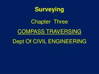
f2 f1 m f' A B b3 a1 b2 b i’ a N N’ V P O S A i a2 a3 b1 d K D O – optical centre of object glass: A – optical centre of anallatic lens P – principal focus of anallatic lens K – distance between object glass and anallatic lens D – distance between vertical axis of instrument and staff S - staff intercept v – vertical axis of the instrument Anallatic Lens - Convex lens between the object glass and diaphragm to make additive constant as zero - Reduces the brilliance of image - Distance = difference in stadia hair x multiplying constant (100) Sivapriya Vijayasimhan
1 Sivapriya Vijayasimhan f - focal length of the objective f1 and f2– conjugate focal lengths of object glass f' – focal lengths of anallatic lens d - distance between optical centre and vertical axis of instrument m - distance between optical centre and real image , ab i– length of image a3b3 when anallatic lens is not provided i ‘– length of image a3b3 when anallatic lens is provided Ray of light from AB along AN and BN’, meets at P P –principal focus of anallatic lens Diverging ray from P emerge direction parallel to axis of telescope after passing through anallatic lens Real image “ab” is formed Without inclusion of Anallatic lens, law of lenses
2 3 in equation 2 With inclusion of Anallatic lens, law of lenses With inclusion of anallatic lens, imaginary object a2b2 is seen. Final image “ab” is formed in stadia hairs Eliminate m,f2 and I, from equation 1 and 2; Sivapriya Vijayasimhan
Substitute values of i and f2 from equation 3 , we get D is proportional to S By adopting suitable values for f,f’,K and i; K’ is derived as follows Sivapriya Vijayasimhan
Errors and Precautions in Tacheometric Surveying Errors of observation Instrument Errors Errors due to natural causes 1.Errors of observation Sivapriya Vijayasimhan
2. Instrument Errors 3. Errors due to natural causes Sivapriya Vijayasimhan