Download
1 / 29
290 likes | 439 Views
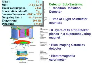
Powering of Detector Systems. Satish Dhawan, Yale University Richard Sumner , CMCAMAC LLC. AWLC 2014, Fermilab May 12 - 16, 2014. Agenda Prior / Current Status LDO Powering Efficiency Buck Converter Frequency limited by FeCo Commercial Devices limited by 200 KHz – 4 MHz - Core losses

E N D
Powering of Detector Systems Satish Dhawan, Yale University Richard Sumner , CMCAMAC LLC AWLC 2014, Fermilab May 12 - 16, 2014
Agenda • Prior / Current Status • LDO Powering Efficiency • Buck Converter • Frequency limited by FeCo • Commercial Devices limited by 200 KHz – 4 MHz - Core losses • Higher Frequency > smaller components • Wireless Charging, Intel 4th Generation Core • Air Core Toroid vs Planar (spirals). PC Traces @ > 100 MHz • Shielding Electrostatic & RF • ATLAS Tracker • Future
Power Efficiency _ Inefficiency _ Wasted Power Power delivery Efficiency= 30 % with Power for Heat Removal = 20 %
Crucial element - Inductor Low DCR for output current Shielding to sensor Cooling
Plug In Card with Shielded Buck Inductor Coupled Air Core Inductor Connected in Series 0.35 mm 1.5 mm 2.5 V @ 6 amps 12 V • Different Versions • Converter Chips • Max8654 monolithic • IR8341 3 die MCM • Coils • Embedded 3oz cu • Solenoid 15 mΩ • Spiral Etched 0.25mm Spiral Coils Resistance in mΩ Noise Tests Done: sLHC SiT prototype, 20 µm AL Shield
Solenoid Copper Coils PCB embedded Coil From Fermilab Talk 041310
Test Silicon Strip Detector GLAST Sensor [Nucl & Instr Meth A 541 (2005)29-39] 64 strips- 228 µm pitch Size 15mm x 35mm Substrate Thickness = 410µm Charge Sensitive Pre-amp Cremat CR-110 Switch Matrix Select 8 strips of 64 For analog output Output Op amp 64 Parallel Al Strips Length = 35 mm Width = 56µm Pitch = 228 µm August 4, 2012
Signal Chain CR110 Q Amp 10 KΩ 2 pF 0.1 µF Pulser 1 KΩ 1 KΩ 50 Ω Scope 50 Ω 50 Ω 50 Ω 1.4 mV / fC x10 X 0.5 X 0.05 Signals 100 mV 5 mV 10 fC 14 mV 140 mV 70 mV Measure 45 mV 1 mip = 7 fC 1 mip = 32 mV August 4, 2012
Top View Side View 12 V Square Waves on Spiral Coil Inductive coupling to strip Capacitive Coupling to Strip 1 cm - Electrostatic Shield For eliminating Charge injection from spiral to strip 20 µm Al foil is OK Signal Induced From spiral to a single strip Net effect is zero + - Gnd Q Amp Gain G = - 3K 1.4 mV / fC G 1.4 pF
RF shielding Measurement of RF field (by eddy current loss) vs distance 34 mil thick 4 layer PCB Spacers 2, 8 & 32 mil thick 36 mm 15 mm 4 mil Copper Tape 4 mil thick Mylar 25 cms x 25 cms Spiral Inductor Measure IC current vs distance between spiral & copper tape Put finger pressure between copper tape and PCB Yale University January 2, 2014
Eddy Current Loss vs Distance between Spiral to Copper Tape Current in mA Distance in mils
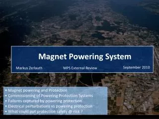
http://www-personal.engin.umd.umich.edu/~chrismi/ Seminar 9: Wireless charging of EV Chris Mi . U of Michigan Car Metal Al Plate 600 mm x 800mm 1 mm thick for mechanical strength Coil - Top Coil - Bottom Frequency = 85 KHz Power transmitted = 10KW Inefficiency without Al shield = 20 % Inefficiency with Al shield = 1 % Power loss in Car metal without Al shield = 2 KW > 15C rise in temperature Power loss in Al shield = 0.1 KW Yale University March 21, 2014
Wireless Power Groups • Automobile Charging • Cell phone Mats - 3 Groups. Each has > 50 companies involved • Wireless Kitchen - ISM Band 6.78 MHz & multiples. GaN
Intel 4th Generation Core Processor: June 2013 • Input = 1.8V • Maximum Current = 700 Amps • Output ~ 1 V Multiple Domains – up to 16 Phases • Turn output On when needed • Inductors on Die / on Package • Efficiency = 90% Mac Pro Air !!!
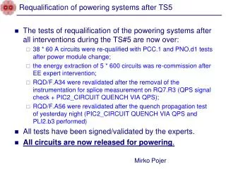
ATLAS DC-DC Powered Stave • STV10 DC-DC Convertor From CERN group • Based on commercial LT chip • 10V in, 2.6V out, up to 5A PCB Toroid Peter W Phillips STFC RAL 14/11/11
Last Proposal to DoE to develop Inductors Another air core Toroid solution An air core Toroid solution with shield 2009 Yale Solution with Embedded air core Spiral inductors in a 4 layer Standard PCB. Not shown an electrostatic 10 µm Al foil Shield Yale version can be made same size as the Toroid solution by changing power connectors Generic / Project funding???
Planar Coil – “Up Close and Personal” Double Trigger Noise (DTN) With Planar Converter With Toroid Converter Approx <3mm from wire bonds with improved reference @ 0.5fC Reference measurement (CERN STV10 converter) @ 0.5fC Ashley Greenall , UK Group • For conducted noise configuration, Planar • coil registers zero occupancy(even at 0.5fC) • Only when close to asics are hits registered, • 3/2 counts at 0.5fC, see above • CERN converter registers zero occupancy until 0.5fC, • then registers 528/244 hits Above picture is Double trigger noise i.e. after a hit ; spurious counts are registered Comments inserted by Yale University Noise in Electrons Measured @ Liverpool cern stv10 noise 589, 604 average = 601 yale planar noise 587, 589 average = 588 noise with dc supplies (no dcdc) = 580 assuming the noise adds in quadrature, extract noise due to dcdc converter: cernstv10 Additional noise = 157 yaleplanar Additional noise = 96 Planar Converter uses the same components except Inductor coil CERN stv Yale Planar Thickness of stv = 8 mm vs 3mm for Planar Shield to Silicon strips are Electrostatics & Eddy current Bottom side shield 2 mm from Planar coil traces Can be mounted on the sensor with 50 µm Kapton Cooling via sensor
Proposed Thinner Converter: Coil No magnetic materials PCB size = 8 mm x 26 mm Question on Air Core Coil (change to oval shape as width is limited) Take this coil and squeeze/ stretch it to 8 mm x 26 mm. wire size 24 - 28 AWG Frequency 2 MHz; Later 10 MHz L = 800 nH Losses are limited by DCR and not ACR. # of turns =? ACR & DCR with wire Gauge Embedded Spirals Disabled for the hand wound coil Height = 2 mm plus shield Toroid Inductor with Shield on toroid height = 8 mm Shield Box Coil Yale Model 2156a PCB size 24mm x 36 mm Coil size 16 mm dia. Embedded in 4 layer PCB. Inner 2 layer spirals are in series is the inductor. 2 versions: Total 6 or 9 turns Hand wound coil (Short solenoid) is 24 AWG. Lower DCR for same inductance 4mm Yale University April 07, 2014
Work in Progress 48 mm 8 mm 22 mm 8 mm Coil to fit in 8 mm x 22mm Embed in PCB?
AWG 24 Winding Frame 8 mm x 22 mm Slot in middle to hold wire g-2 Ribbon 9 mils x 90 mils 5 turns. Inductance = 715 nH DCR = <100 mΩ • Lower Inductance • 2 turns vs 5 turns • Higher Ripple current • Shield distance is higher • More lost power in shield Yale University May 10, 2014
Simulations s. Kalani UCL; UK Atlas Group We want to understand the efficiency costs of the external shield for the planar coils. For a given planar coil we would like a plot of the energy loss in the shields as a function of distance from the coil. There should be a shield on each side of the coil placed symmetrically. The inductance of the coil changes as the distance to the shields changes. Since the ripple current is inversely proportional to the inductance this must be included in the calculation. I expect that the energy loss in the shield will be linearly proportional to the ripple current but we should check this by simulating two different ripple currents for the same configuration. For each coil configuration we would like to plots, inductance and energy loss over a range of shield distances from 0.5 mm to 10 mm with appropriate step sizes. The energy loss plot should be for 1 amp at the 10 mm spacing, with the current increasing as the inductance decreases. The frequency should be 2 MHz. Use five mill thick copper for the shields. Start with the standard nine turn two layer coil and see how it goes. After that we will want to try other coil configurations and possibly other shield thickness and material.
Semtech SC220: 20 MHz 0.6 Amps: North / South Coils for far Field cancellation DCR becomes a problem High Frequency Input = 5 V Enpirion EL711: 18 MHz 0.6 Amps
GaN Update • 600 Volt is the holy grail • EPC is the only one delivering Devices thru distribution • LM5113: driver for eGaN • 1Q2015: Half bridge. ( 2LM5113 + FETS) in 6 mmx 5mm x 1.5mm. 5 -10 MHz External PWM • GaN driver on FET Die Several companies. Panasonic Roadmap 2016
Why Yale design needs GaN • No magnetic materials – All instruments in 4 Tesla magnetic field • Design Goal = Size of converter 8 mm x 26 mm x 4 mm thickness including eddy current shield • Vin = 12 V: Vout = 2.5 V / 1.5 V: I_out = 3 Amps Frequency = 2 MHz • Toroid leak H fields: Spiral /Planar 2 layer 9 turn > Inductance = 800 nH • Need Low DCR & Lower mass to reduce noise created by protons passing thru inactive material • Lower ripple current limits H field range > thinner package • Why GaN ? High frequency > smaller inductor & passives. Smaller foot print For GaN NDA Current Design / Status Yale design thickness is ok. Foot print Ok for circuit only but no room for inductor CERN design size is ok but thickness = 9 mm Size of PCB = 23 mm x 35 mm x 1.5 mm plus shield Spiral inductor embedded in 4 layer PCB. Spirals are 15 mm dia. New Design What GaN Buys us Higher operating frequency > smaller air core inductor & lower DCR Higher efficiency > Lower heat loss Smaller package PowerSoC technology Shield Box Coil 4mm Fold Coil > Squeeze 2 layer spiral to oval shape Short Solenoid > Low DCR Oval Aircore Toroid Yale University April 15, 2014
Closing Remarks • 48 V into Detector: 2 Stages • IC 2 step: 12 V > 1.2V High efficiency • GaN: Driver on Die may be Rad Tolerant • Need lower power loss in detector