Download
1 / 11
150 likes | 438 Views
The 32 T superconducting magnet. H.W. Weijers Users Committee Meeting, Tallahassee, FL October 10-11, 2014. The 32 T magnet: a user magnet. Cold Bore 32 mm Uniformity 1 cm DSV 5·10 -4 Total inductance 254 H Stored energy 8.6 MJ Ramp to 32 T 1 hour

E N D
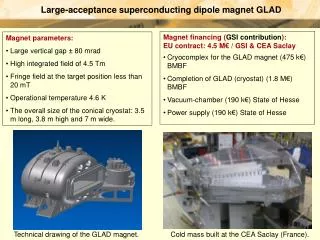
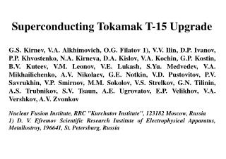
The 32 T superconducting magnet H.W. Weijers Users Committee Meeting, Tallahassee, FL October 10-11, 2014
The 32 T magnet: a user magnet Cold Bore 32 mm Uniformity 1 cm DSV 5·10-4 Total inductance 254 H Stored energy 8.6 MJ Ramp to 32 T 1 hour Lifetime cycles50,000 Mass 2.3 ton 2.5 m Dilution refrigerator or VTI NbTi 15 T / 250 mm bore LTS magnet 17 TREBCOcoils Nb3Sn 32 T will spend most of its life ramping up and down at 4.2 K 0.9 m
Vendor/collaborator updates • HTS Conductor • SuperPower has deliveredthe 12.3 km ordered • MagLab performed QA of all 152+ piece lengths • Most conductormeets expectations, except Cu area • Working on resolution with vendor Controlled atmosphere storage cabinet with conductor spools 152 piece lengths ordered 9 rejected 161 received At MagLab
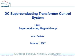
Vendor/collaborator updates • LTS 15 T Outer magnet • All coils ready for implementation of protection circuit, system assembly and factory test in Dec 2014 • MagLab acceptance test planned for 1Q 2015 • Have 3D model of magnet, cryostat, agreed interfaces 0.25 m < Coils on baseplate Magnet support structure > 0.64 m Images courtesy of Oxford Instruments
HTS Technology updates • 2013: Coil 1 prototype (6/20 modules) built and tested • Confirm viability of concept (dry winding, quench protection heaters,…) • Identified areas for rework(done) • Developed initial design of HTS protection circuit 2014: Coil 1 prototype rebuilt, Coil 2 prototype built (6/36 modules) 2 rounds of testing on combined prototypes in 45 T Hybrid Outsert Dielectric failure in heater insulation in first round, solved (improved) Ambitious test goals: took all the data we wanted to get Quench initiation and protection: no surprises Load cycling: no ill effects observed Very repeatable small hysteresis in central magnetic field: seems manageable AC-(ramping) loss: less than assumed per model used in 32 T heat load budget Investigating observed voltage spikes Coil 1 prototype with instrumentation Prototypes include all features of real coils for 32 T except length (#modules)
HTS Technology updates • 2014:Coil 1prototype rebuilt, Coil 2prototypebuilt(6/36 modules) • 2 rounds of testing on combined prototypes in 45 T Hybrid Outsert Prototypes 45 T Hybrid Resistive coils removed to provide space for test cryostat 250 mm
HTS Technology updates • 2014: Coil 1 prototype rebuilt, Coil 2 prototype built (6/36 modules) • 2 rounds of testing on combined prototypes in 45 T Hybrid Outsert • Dielectric failure in heater insulation in first round, solved &improved heaters • Ambitious test goals:took all the data we wanted to get < New quench heaters for Coil 1 prototype
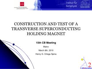
Combined prototype test results • Quench initiation and protection: • no surprises, no degradation after > 84 quenches • Load cycling: no ill effects observed • After 20 cycles at 100% of design stress, 40 cycles at 110%, 2 cycles at 120% • Very repeatable small hysteresis in central magnetic field • Seems manageable • AC-(ramping) loss: less than expected • Per model used in 32 T heat load budget Coil 1 and Coil 2 combined prototypes <Bottom view Side view > 200 mm Fits in 250 mm
HTS Technology updates • 2014: Coil 1 prototype rebuilt, Coil 2 prototype built (6/36 modules) • 2 rounds of testing on combined prototypes in 45 T Hybrid Outsert • Dielectric failure in heater insulation in first round, solved (improved) • Ambitious test goals:took all the data we wanted to get • Coils are robust • Analyzing data • Investigating observed voltage spikes • Benchmarking quench code against data • Disassembling prototypes for inspection < New quench heaters for Coil 1 prototype Coil 2 prototype module after test >
Remaining main risks Project risksthat are addressed or at least significantly reduced: Diamagnetic Helium (“bubble”),quench heater/protection failure, load cycling degradation, failure to test prototypes properly, test bed for 32 T coils, high joint resistance, shielding currents, conductor cost and availability, quench in HTS alone
32 T: Summary and outlook • Ambitious technology development and construction project • Not low-risk • Confident in viability of our technology choices • Confirmed with prototype coil testing • REBCO conductor from SuperPower received • 15 T Outsert nearing completion • Factory test planned for December 2014 • HTS-LTS quench subject of continued study • After successful completion of prototype phase: • Production readiness review • HTS coil winding & assembly • Integration with Outsert • System test in Dec 2015 (best case), 1-2 Q 2016 (more likely)