Download
1 / 19
240 likes | 441 Views
Gas Turbines and Combined Cycle Power Plants. 130 BC - Hero of Alexandria’s reaction steam turbine 1550 – Leonardo da Vinci’s “smoke mill” 1629 – Giovanni Branca’s impulse steam turbine

E N D
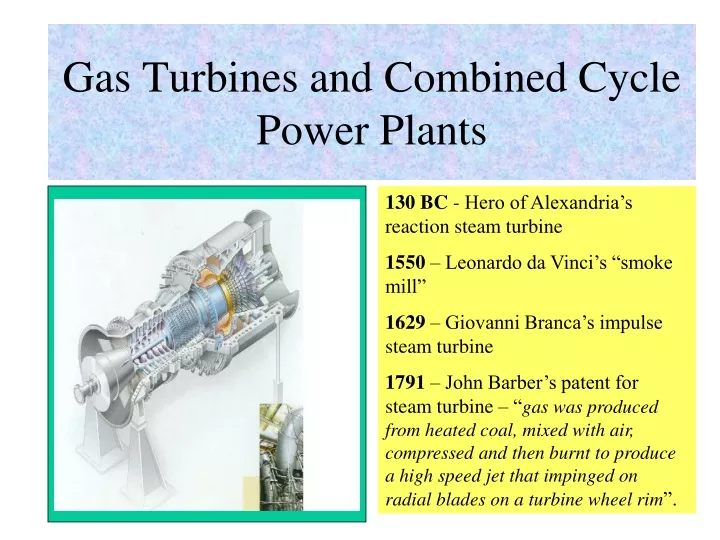
Gas Turbines and Combined Cycle Power Plants 130 BC - Hero of Alexandria’s reaction steam turbine 1550 – Leonardo da Vinci’s “smoke mill” 1629 – Giovanni Branca’s impulse steam turbine 1791 – John Barber’s patent for steam turbine – “gas was produced from heated coal, mixed with air, compressed and then burnt to produce a high speed jet that impinged on radial blades on a turbine wheel rim”.
Gas Turbines, Its Uses and History • Aero-Derivative Gas Turbine Developments • Operating Principle of a Gas Turbine • Ideal & Non-Ideal Brayton Cycle, Its Efficiency • Effects of Varying Compression Ratio • Modifications to Improve Efficiency • Gas Turbine Fuels • Gas Turbine Technologies • Advantages, Disadvantages of GT • Environmental Impact, Risks of GT Topics – Simple Gas Turbines
A. Gas Turbine – its evolution • 1808 – Jun Dumball - multi-stage turbine with only moving blades without stationary airfoils to turn the flow into each succeeding stage • 1837 – Bresson - thought of a fan to drive pressurized air into a combustion chamber, combustion products cooled with additional air, and final product was used to drive turbine blades. • 1872 – Dr. Franz Stolze - combined the ideas of Barber and Dumball to develop the first axial compressor driven by an axial turbine. • 1884 – Sir Charles Parsons - patented a reaction steam turbine and gas turbine • 1888 – Charles de Laval’s – only with his application of Giovanni Branca’s idea for an impulse turbine did a workable hardware emerge. • 1895 –August Rateau, Charles Curtis and Dr. Zoelly adapted variations in the impulse turbine to gas turbines.
Evolution of the Gas Turbine • 1900-1904 – Dr. Stolze - designed and built a multi-stage axial flow compressor, a single combustion chamber, a multi-stage axial turbine, and a regenerator utilizing exhaust gases to heat the compressed air; the unit was tested but never ran successfully due to problem with efficiency of compressor and turbine. • 1903 – Rene Armengaug and Charles Lemale - built and successfully tested in Paris a gas turbine using a Rateau rotary compressor and a Curtis velocity compounded steam turbine. • 1905 – Brown Boveri – built the first gas turbine and compressor unit for a refinery in Philadelphia – 5,300 kW. Boveri also built a 4,000 kW turbine – the world’s first electricity generating turbine for a power station in Switzerland.
Aero-Derivative GT Developments • 1930 – Frank Whittle - filed patent for “Improvements in Aircraft Propulsion” – a compound axial centrifugal compressor and a single axial stage turbine. • 1935 – Germany’s Hans Pabst von Ohain and aircraft manufacturer Ernst Heinkel – built the first turbojet engine, a compound axial-centrifugal compressor and a radial turbine for an aircraft. • 1959 – Cooper Bessemer - installed the world’s first base-load aero-derivative industrial gas turbine FT3 (10,500 BHP) to drive a pipeline compressor. • Jet engines developed from the gas turbine and became the modern aircraft engines for the world’s airline fleets. • Heavy-frame and aero-derivative gas turbines intended solely for power generation developed from aero engines.
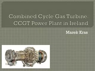
Operating Principle of a Gas Turbine • A flow of air is manufactured, instead of relying on nature (wind). • The airflow then powers a windmill or air turbine, generating rotary motion for driving a machine. • A compressor compresses air, which is then released through an enclosed set of windmill blades (turbine) • A combustion stage burns fuel in the compressed air to raise its temperature before it is released to the turbine adding mechanical output and generating sufficient mechanical energy to drive the compressor as well. Inlet duct, Compressor, Combustion Chamber, Turbine, Exhaust Diffuser, Shaft, Journal & Thrust Bearing, Lubrication
Micro Turbines The Capstone MicroTurbine™ System
Effect of Compression Ratio The two optimum pressure ratios, for efficiency and specific power, are not the same, and this necessitates a compromise in the design to obtain optimum economic benefits.
Modified Brayton Cycle: regeneration, compressor intercooling, reheating, water injection
Modifications to Improve Power Output and Efficiency • Raise hot gas temperature T3 – to what metallurgy could withstand. • Regeneration – internal exchange of heat within the cycle to preheat the compressed gas at [2] by the exhaust gases at [4] in a surface-type heat exchanger called regenerator or recuperator. A 3.2-MW GT for power generation claimed efficiency of 40.5% with recuperation (US DOE). • Compressor intercooling – as the air is compressed, it heats up so that cooling is needed to reduce compressor work • Turbine reheat – keeping the gas temperature high will raise turbine output • Mass injection – adding water will materially increase power output while efficiency is only marginally increased. (1) Water injection into the compressor reduces air temperature and compressor work similar to intercooling. (2) Injecting heated water (using exhaust heat) before regenerator to saturate the compressed air raises mass flow of gas which raises turbine output without increasing compressor work.
Gas Turbine Fuels • Stationary gas turbines can be fired with a variety of gases like: • gasified coal and biomass (IGCC) • methane from sanitary landfill and biogas digesters • hot gases from pressurized fluidized bed combustion (PFBC) and solid oxide fuel cell (SOFC) • natural gas or liquified natural gas (LNG) • heavy diesel oil and fuel oil • For mobile applications like aviation: • aviation turbine fuel (basically kerosene with anti-static and anti-freeze additives)
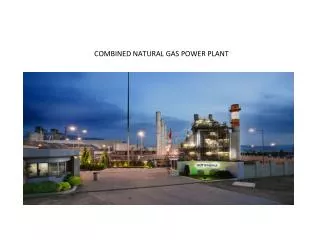
Gas Turbine Technologies • Aero-derivative GTs (35 – 45 MW) – lighter, more reliable, fires at higher air temperature (1300 C) hence more efficient (38 – 42%), but costs more and are more expensive to maintain • Heavy frame GTs (> 200 MW) – heavier, less reliable than aero-derivate, fires at lower temperature hence less efficient (30-35%) but cost less and are less expensive to maintain • Advanced heavy frame GTs – available and continuously being improved: regeneration or recuperation, compressor intercooling, turbine reheating and mass injection • Humid air turbine (HAT) – injecting water vapor into the compressed air before the GT combustion chamber increases efficiency of aero-derivate GTs • Cascaded humid air turbine (CHAT) – incorporating humid air, intercooling and reheat, efficiency of 44.5% and costs $800/kW for 11-MW unit; a 300-MW unit costs $375/kW with estimated efficiency of 54.7%.
Advantages & Disadvantages of GT • Advantages of GT power plant - low specific cost - low emission levels, if high quality fuel is used - can be constructed easily (12 months or less) - high availability and reliability - can start easily • Disadvantages of GT power plant - low thermal efficiency (~35% for heavy frames and 42% maximum for aero-derivative) - generally needs clean fuel, although some older models can run with HFO with penalty on availability
Environmental Impact of GT • Environmental impact of GT power plant - SOX: generally low or even nil if very low sulfur fuel, e.g. natural gas is used - NOX: low due to use of water injection or steam when liquid fuel fired or dry low NOX emission controller when firing gas - CO: lower than for coal-fired plant - CO2: lower than for coal-fired plant - Particulate: lower than for coal-fired plant - Noise: low, especially if acoustic walls are used
Risks with GT and CCGT • Risks associated with GT Technology – GT is extremely reliable, efficient and robust machine since safety and reliability are of prime importance in the airline industry. - Aero-derivative GTs should show the same levels of reliability and efficiency provided no significant design modifications are made; low risk - Heavy-frame GTs developed specifically for power generations do not have the same exacting standards as aviation units; low to medium risk • Risks associated with the cost and supply of fuel – Natural gas appears to be the fuel of the moment as prices remain low. But once prices start to rise, coal-fired power plants, even with expensive emission control systems, will soon become attractive. New technologies to gasify coal and use in GT offer some hope; low to medium risk