Download
1 / 24
240 likes | 481 Views
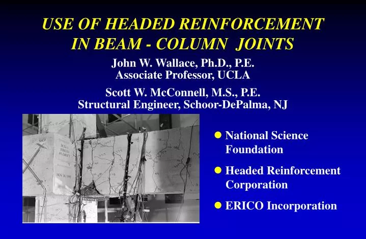
USE OF HEADED REINFORCEMENT IN BEAM - COLUMN JOINTS. John W. Wallace, Ph.D., P.E. Associate Professor, UCLA Scott W. McConnell, M.S., P.E. Structural Engineer, Schoor-DePalma, NJ. National Science Foundation Headed Reinforcement Corporation ERICO Incorporation.

E N D
USE OF HEADED REINFORCEMENT IN BEAM - COLUMN JOINTS John W. Wallace, Ph.D., P.E.Associate Professor, UCLA Scott W. McConnell, M.S., P.E.Structural Engineer, Schoor-DePalma, NJ • National Science Foundation • Headed Reinforcement Corporation • ERICO Incorporation
HEADEDREINFORCEMENT ? • Plate Anchor Rectangular/Round • Threaded/Friction Weld • Area = 5 to 10 Bar Area • Beam-Column Joints Standard Hooks • Ease of Fabrication & Placement
AVAILABLE INFORMATIONAnchorage/Beam-Column Joints • UCLA & Clarkson UniversityWallace, McConnell, Gupta Reports/ACI Papers (1994, 1997, 1998) Also Yu (2001) • University of Texas, AustinJirsa, Devries, BashandyPh.D. Dissertations (1996), ACI Paper (1999) • University of KansasMcCabe, Wright, Wu (Reports, 1997)
PROJECT OVERVIEW EXTERIOR ROOF& CORNER JOINTSEXTERIOR INTER-STORY JOINTS
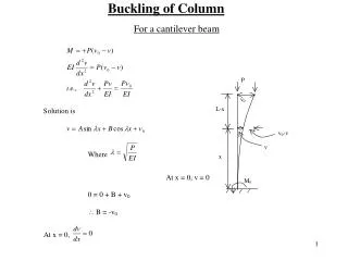
³ å M / M 1 . 2 (1.1 Test) column beam = - ' A 0 . 3 sh ( A / A 1 ) f / f sh c g ch c y = A / A 1 . 51 (test) sh , provided sh , req ' d f = = V ( 0 . 85 )( 12 ) 4000 (psi) ( 16 " )( 13 . 5 " ) 140 kips n = ± = 2 V ( A in )( 1 . 25 )( 60 ksi ) P 75 to 140 kips u s beam f = V / V 0 . 5 to 1 . 0 u n DESIGN REQUIREMENTSExterior Roof Connections • Strong Column - Weak Beam (352-01) • Joint Confinement Reinforcement (352-01) • Joint Shear Stress Limits (352-91)
= = = = = ' ' ' ' l l 0 f . 02 d d / 65 f / f f (psi) (psi) 1200 925 d d / / f f (psi) (psi) 14.6 d db dh y b b y c c b d c c b = = l / l ( 18 to 22) d / 14 . 6 d 1 . 23 to 1.5 = = = ' l (0.75) l 900 d / f (psi) 14 . 23 d dh b b provided d db d c b = = l / l (18 to 22)/14.23 1 . 25 to 1.55 provided d DESIGN REQUIREMENTSExterior Roof Connections • Anchorage Requirements • Tension (318 Eq. 21-5, 352-91) • Compression (318 S12.3)
Specimen DamageExterior Roof Connections KJ16 - Top Bar Pull-out
REINFORCING DETAILSExterior Roof Connections Restraint Bars Restraint Bars Top View Side View
³ å M / M 1 . 2 (1.7 Test) column beam = - ' A 0 . 3 sh ( A / A 1 ) f / f sh c g ch c y = A / A 1 . 17 (test) sh , provided sh , req ' d f = = V ( 0 . 85 )( 15 ) 4000 (psi) ( 18 " )( 18 " ) 260 kips n = - = 2 V ( 4 x 0 . 79 in )( 1 . 25 )( 60 ksi ) V 207 kips u column f = V / V 0 . 80 u n DESIGN REQUIREMENTSExterior Inter-Story Connections • Strong Column - Weak Beam (352-01) • Joint Confinement Reinforcement (352-01) • Joint Shear Stress Limits (352-91)
= = = ' ' l f d / 65 f (psi) 925 d / f (psi) 14.6 d dh y b c b c b = = l / l 13 d / 14 . 6 d 0 . 9 (0.82 per 352) provided dh b b = = ' ' l 0 . 02 d f / f (psi) 1200 d / f (psi) db b y c d c = = = ' l (0.75) l 900 d / f (psi) 14 . 23 d d db d c b = = l / l 13/14.23 0.91 provided d DESIGN REQUIREMENTSExterior Inter-Story Connections • Anchorage Requirements • Tension (318 Eq. 21-5, 352-91) • Compression (318 S12.3)
Beam End RotationExterior Interstory Connections BCEJ1 - Drift Level 6% Potentiometer Potentiometer
Specimen DamageExterior Interstory Connections Bottom Bar Push-Out @ 6% BCEJ1 - Drift Level 6%
Compression Bar Push-OutExterior Inter-Story Connections • Beam Moment Capacity Compression Steel • Slight Pushout Occurs Redistribution From Steel to Concrete • Minor Reduction in Beam Moment Capacity • Note - Compression ld Satisfied by Checking Tension ld
Summary ObservationsHeaded Bars in Beam-Column Joints • Required Embedment Length Kansas Study: ld =0.60 ldhTexas Study: ld = (0.60 - 0.70) ldhUCLA/Clarkson Large-Scale Study: ld =0.82 ldh • Other Design Requirements Flexural Strength Ratio: Mcolumn /Mbeam > 1.2 Joint Shear Emdedded Bars Must Be Shoved To Back of Joint • Practical Recommendation for Emdedmentld =0.75 ldh
CONCLUSIONS • Beam-Column Joint Tests • Six Specimens (3 Exterior, 3 Roof) • Small Cover/Need for Transverse Steel • Push-Out of Compression Bars • ACI Committee 352 Draft Report • Modified to Allow Use of Headed Bars • Research Needs - Cyclic Loading • Cover/Transverse Reinforcement • Multiple Layers of Reinforcement