Programmable logic devices
410 likes | 1.27k Views
Programmable logic devices. Outline. PLAs PALs ROMs. Programmable Logic Device. A programmable logic device (PLD) is an integrated circuit with internal logic gates that are connected through electronic fuses.

Programmable logic devices
E N D
Presentation Transcript
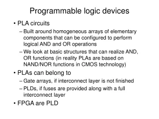
Outline • PLAs • PALs • ROMs Programmable Logic Device
Programmable Logic Device A programmable logic device (PLD) is an integrated circuit with internal logic gates that are connected through electronic fuses. • Programming the device involves the blowing of fuses along the paths that must be disconnected so as to obtain a particular configuration. • The word programming refers to a hardware procedure that specifies the internal configuration device. • The gates in a PLD are divided into an AND array and OR array that are connected together to provide an AND-OR sum of Product implementation. • The initial state of a PLD has all the fuses intact. Programmable Logic Device
PLDs There are three types of PLDs. They are differ in the placement of fuses in the AND-OR array as shown below. Programmable Logic Device
Types of PLDs Programmable Logic Device
PLDs The most flexible PLD is the programmable logic array (PLA), where both the AND and OR arrays can be programmed. The product terms in the AND array may be shared by any OR gate to provide the required sum of products implementation. Programmable Logic Device
Programmable logic arrays (PLAs) A block diagram of the PLA shown below consists of n inputs, m outputs, k product terms, and m sum terms. The product terms constitute a group of k AND gates and the sum terms constitute a group of m OR gates. Programmable Logic Device
PLAs A typical PLA has 16 inputs, 48 product terms, and 8 outputs. The number of programmed fuses is 2n k + k m. There two types of PLAs: • mask-programmable PLA -- custom-made PLA • field-programmable PLA (FPLA) -- programmed by a user Programmable Logic Device
Internal Construction of a PLA. Programmable Logic Device
Example F1 = AB' + AC and F2 = AC + BC Programmable Logic Device
Examples • Implement the following Boolean expressions: F0 = A + B'C', F1 = B'C' + AB, F2 = AC' + AB, And F3 = B'C + A • PLA implementation of a 2-bit multiplier. • Design a function generator of three inputs that implements the logic functions AND, OR, NAND, NOR, XOR, and XNOR: Programmable Logic Device
Programmable Arrays Logic (PALs) A programmable array logic (PAL) is a programmable logic device with a fixed OR array and a programmable AND array. The PAL is easier to program but not as flexible as the PLA. The typical PAL usually limits the number of inputs to an OR gate to 2, 4, 8, or 16. Examples: • BCD to Gray-code converter • Two-bit comparator Programmable Logic Device
Read-Only Memories (ROMs) An read-only memory (ROM) is a device that includes both the decoder and the OR gates within a single IC package. The connections between the outputs of the decoder and the inputs of the OR gates can be specified for each particular configuration. The ROM is used to implement complex combinational circuits within one IC package or as permanent storage for binary information. Programmable Logic Device
Read-Only Memories (ROMs) • ROMs come with special internal electronic fuses that can be programmed for a specific configuration. Once the pattern is established, it stays within the unit even when power is turned off and on again. • A ROM consists of n input lines and m outputs lines. • Each bit combination of the input variables is called an address. • Each bit combination that comes out of the output lines is called a word. • The number of bits per word is equal to number ofoutput lines m. Programmable Logic Device
Read-Only Memories (ROMs) • An address is essentially a binary number that denotes one of the minterms of n variables. • The number of distinct addresses possible with n input variables is 2n. • An output word can be selected by a unique address, and since there are 2n distinct addresses in a ROM, there are 2n distinct words that are said to be stored in the unit. • A ROM is characterized by the number of words 2n and the number of bits per word m. Programmable Logic Device
ROMs Programmable Logic Device
Example • A 328 ROM consist of 32 words of 8 bits each. This means there are eight output lines and that there are 32 distinct words stored in the unit. The particular word selected that is presently available on the output lines is determined from the five inputs lines. • A ROM is sometimes specified by the total number of bits it contains, which is 2n m. For example, a 2048-bit ROM may be organized as 512 words of 4 bits each. This means that the unit has four output lines and 9 input lines to specify 29 = 512 words. The total number of the bits stored in the unit is 5124 = 2048. Programmable Logic Device
Example Design a combinational circuit using a ROM. This circuit accepts a 3 bit number and generates an output binary number equal to the square of the input number. Programmable Logic Device
Example Design a one-bit full adder using ROM. Programmable Logic Device
Types of ROMs • Mask programming • Programmable read-only memory (PROM) • Erasable PROM (EPROM) Programmable Logic Device
Exercises p.380 5.1, 5.2, 5.3 Programmable Logic Device