Download
1 / 19
270 likes | 865 Views
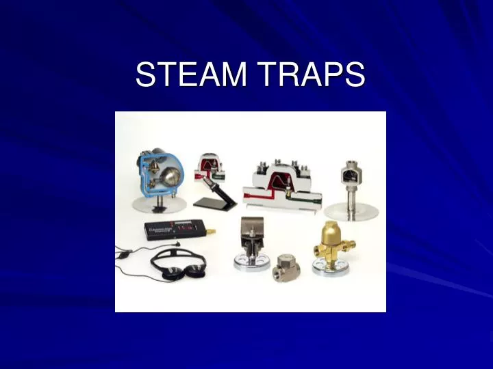
STEAM TRAPS. Trap Basics. Whenever possible, steam traps should be located ~2 foot from, and below the discharge of the equipment. Strainers, whether built in or separate, are recommended with all steam traps.

E N D
Trap Basics • Whenever possible, steam traps should be located ~2 foot from, and below the discharge of the equipment. • Strainers, whether built in or separate, are recommended with all steam traps. • Install ball (or gate) valves before and after the steam trap to ease maintenance by isolating the trap from the rest of the system.
Trap Basics • Unions should be installed between the isolating valves and steam trap so that the trap can be easily removed and replaced as required. • Blowdown valves are recommended at strainer outlet • A test valve or a sight flow indicator are recommended to determine if system is operating and functioning properly
Pipe Scale & Dirt • When new piping is installed, chunks of solder, fragments of metal parts, packing, and even nuts and bolts are often left inside. • In older piping systems, there is a build-up of scale and dirt that can break free and travel through the steam system. • Pipe scale and dirt can permanently damage steam equipment, especially steam traps. To overcome this: • Install a strainer prior to every steam trap • Utilize a dirt pocket in front of the trap to accumulate dirt and scale.
Steam Main Drip Leg • Steam main drip pockets are recommended at every horizontal and vertical change of direction in piping, and in front of all equipment such as control valves, PRVs, or shut off valves because these are natural collection points. • The distance between drain pockets should decrease as the steam main size increases because of the additional amount of energy (water hammer) larger mains have that could cause damage. • A rule of thumb for spacing drip pockets is the higher the pressure or larger the main, the closer the spacing.
Steam Main Drip Leg • For steam main up to 6”, a full size drip leg should be installed. Over 6”, a collecting leg of ½ of the pipe size can be utilized, as long as it is not under 6” • The take off of the steam trap should be at a point ~3” above the lower level of the drip leg, draining by gravity
Back Pressure Effect • The general rule of thumb for calculating the back pressure of condensate lift installations is 1psig back pressure for each 2 foot of vertical lift. For low pressures, use 1psig per foot for lift.
Bypass Loops • Bypass loops are needed when the trap capacity can not meet the start-up requirements. • CAUTION: Bypass could be inadvertently left open, allowing large amounts of live steam to be lost when hot running load is achieved. • Most steam trap manufactures discourage the use of bypass loops. By selecting a trap with high start-up capacity, the bypass is not needed.
Traps in Parallel • Parallel traps are used in critical process applications where the unit can not be shut down for servicing. One trap can be on while the other is serviced. • Good alternate to the bypass loop installation because it eliminates the possibility of blowing live steam through an inadvertently open bypass valve. • Negative: More Expensive
Space Heating Equipment • In order to facilitate good drainage from the equipment, a vertical leg (at least 12” long) should be installed on the bottom of the equipment. • If the unit heater has a modulating valve on the inlet, consideration must be given to the ΔP across the trap so that there is always enough steam pressure to remove condensate.
Space Heating Equipment • The installation of a vacuum breaker is vital whenever steam is controlled to the unit heater with a modulating control valve. • An air vent installed at the opposite corner from the inlet steam supply helps remove air from the remote areas of the equipment.
Shell & Tube Heat Exchangers • Optional vacuum breaker installed to allow free drainage of condensate when system is off. • The air vent is used to remove the air that may be introduced through the opening of the vacuum breaker or from the steam supply.
Delta Cycle-Start up • At cold start up, stem is full open to allow high flow capacity • Only one moving part for simple design
Delta Cycle-Closing • Stem starts to close as condensate temperature increases • Flow will modulate as condensate is formed
Delta Cycle-throttle • Stem throttles shut when condensate reaches temperature of saturated steam • Expansion chamber allows extra capacity before shut off
Delta Cycle-Shut off • Stem is tightly shut when steam is present • Single, open blade design allows faster response to temperature changes