Download
1 / 24
240 likes | 353 Views
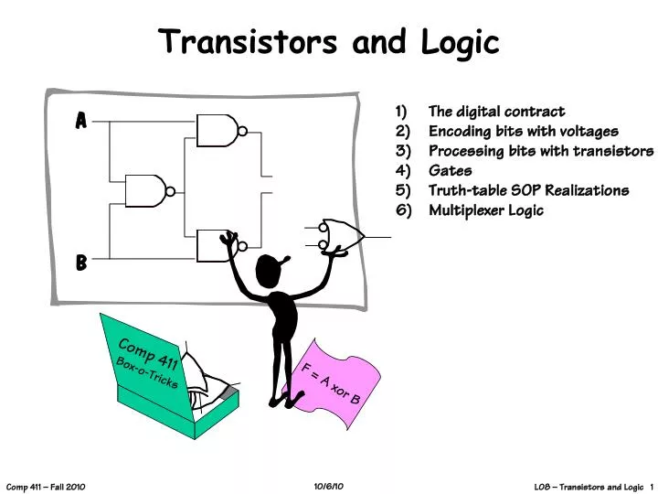
A. B. Comp 411 Box-o-Tricks. F = A xor B. Transistors and Logic. The digital contract Encoding bits with voltages Processing bits with transistors Gates Truth-table SOP Realizations Multiplexer Logic. But, what PROCESSES all these bits?. Where Are We?. Things we know so far -

E N D
A B Comp 411 Box-o-Tricks F = A xor B Transistors and Logic • The digital contract • Encoding bits with voltages • Processing bits with transistors • Gates • Truth-table SOP Realizations • Multiplexer Logic
But, what PROCESSES all these bits? Where Are We? Things we know so far - 1) Computers process information 2) Information is measured in bits 3) Data can be represented as groups of bits 4) Computer instructions are encoded as bits 5) Computer instructions are just data 6) We, humans, don’t want to deal with bits… So we invent ASSEMBLY Language even that is too low-level so we invent COMPILERs, and they are too rigid so …
1 1 0 1 0 0 1 1 0 1 0 0 A Substrate for Computation • We can build devices for processing and representing bits using almost any physical phenomenon Wait! Those last ones might have potential... neutrino flux trained elephants engraved stone tablets orbits of planets sequences of amino acids polarization of a photon
Using Electromagnetic Phenomena Things like: voltages phase currents frequency For today let’s discuss using voltages to encode information. Voltage pros: easy generation, detection voltage changes can be very fast lots of engineering knowledge Voltage cons: easily affected by environment need wires everywhere
Representing Information with Voltage • Representation of each point (x, y) on a B&W Picture: • 0 volts: BLACK • 1 volt: WHITE • 0.37 volts: 37% Gray • etc. • Representation of a picture: • Scan points in some prescribed raster order… generate voltage • waveform How much information at each point?
Copy v v INV v 1-v Information Processing = Computation • First, let’s introduce some processing blocks:(say, using a fancy photocopier/scanner/printer)
(Reality) Copy INV Copy INV input Copy INV (In Theory) Copy INV Let’s build a system! ? output
Why Did Our System Fail? • Why doesn’t reality match theory? • 1. COPY Operator doesn’t work right • 2. INVERSION Operator doesn’t work right • 3. Theory is imperfect • 4. Reality is imperfect • 5. Our system architecture stinks • ANSWER: all of the above! • Noise and inaccuracy are inevitable; we can’t reliably reproduce infinite information-- we must design our system to tolerate some amount of error if it is to process information reliably.
Contracts Every system component will have clear obligations and responsibilities. If these are maintained we have every right to expect the system to behave as planned. If contracts are violated all bets are off. The Key to System Design • A SYSTEM is a structure that is guaranteed to exhibit a specified behavior, assuming all of its components obey their specified behaviors. • How is this achieved?
The Digital Panacea ... • Why DIGITAL? • … because it keeps the contracts SIMPLE! • The price we pay for this robustness? • All the information that we transfer between components is only 1 crummy bit!But, in exchange, we get a guarantee of a reliable system. 0 or 1
0/1 Noise The Digital Abstraction “Ideal”Abstract World RealWorld ManufacturingVariations Bits Volts or Electrons or Ergs or Gallons Keep in mind, the world is not digital, we engineer it to behave that way. We must use real physical phenomena to implement digital designs!
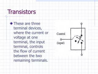
Static Discipline input A input B output Y input C A Digital Processing Element • A combinational device is a circuit element that has • one or more digital inputs • one or more digital outputs • a functional specification that details the value of each output for every possible combination of valid input values output depends only on the latest inputs • a timing specification consisting (at minimum) of an upper bound tpd on the time the device will take to produce the output value from stable valid input values Output a “1” if at least 2 out of 3 of my inputs are a “1”. Otherwise, output “0”. I will generate a valid output in no more than 2 minutes after seeing valid inputs
No feedback (yet!) A Combinational Digital System • A system of interconnected elements is combinational if • each circuit element is combinational • every input is connected to exactly one outputor directly to a source of 0’s or 1’s • the circuit contains no directed cycles • But, in order to realize digital processingelements we have one more requirement!
Valid “0” Valid “1” Forbidden Zone volts Invalid Min Voltage CONSEQUENCE: Notion of “VALID” and “INVALID” logic levels Max Voltage Noise Margins • Key idea: Don’t allow “0” to be mistaken for a “1” or vice versa • Use the same “uniform representation convention”, for every component in our digital system • To implement devices with high reliability, we outlaw “close calls” via a representation convention which forbids a range of voltages between “0” and “1”.
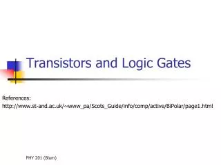
I will only output a ‘1’ if an odd number of my inputs are ‘1’ I will only outputa ‘1’ if all my inputs are ‘1’ I will copy andrestore my inputto my output I will output thecomplement of my input I will output a ‘1’ if any of my inputs are ‘1’ AND XOR OR Digital Processing Elements • Some digital processing elements occur so frequently that we give them special names and symbols A Y A Y buffer inverter A A Y Y B B A Y B
AND XOR OR Digital Processing Elements • Some digital processing elements occur so frequently that we give them special names and symbols A Y A Y buffer inverter A A Y Y B B A Y B
From What Do We Make Digital Devices? • Recall our common thread from Lecture 2… • A controllable switch is a common link of all computing technologies • How do you control voltages with a switch? • By creating and opening paths between higher and lower potentials This symbol indicates a “high” potential, or the voltage of the power supply Load This symbol indicates a “low” or ground potential
S D “ “ S D S D N-Channel Field-Effect Transistors (NFETs) When the gate voltage is high, the switch “closes” (connects). Good at pulling things “low”. D D + G G VDS³ 0 + - S - S Operating regions: cut-off: VGS < VTH linear: VGS³ VTH VDS < VDsat saturation: VGS³ VTH VDS³ VDsat VGS 0.8V IDS linear saturation VGS VGS - VTH VDS
S D “ “ S D S D P-Channel Field-Effect Transistors (PFETs) When the gate voltage is low, the switch “closes” (connects). Good at pulling things “high”. S - S VGS - + G G VDS 0 + D D Operating regions: cut-off: VGS > VTH linear: VGSVTH VDS > VDsat saturation: VGSVTH VDSVDsat –0.8V -VDS -VGS VGS - VTH saturation linear -IDS
We’ll usePFETs here pulldown: make this connectionwhen VIN is near VDD so that VOUT = 0 and, NFETshere Finally… Using Transistors to Build Logic Gates! VDD Logic Gate recipe: pullup: make this connectionwhen VIN is near 0 so that VOUT = VDD VIN VOUT
Valid “1” Invalid Valid “0” “1” “0” only a narrow range of input voltages result in “invalid” output values. (this diagram is greatly exaggerated) “0” “1” A Y inverter CMOS Inverter Vout Vin Vout Vin
A A B B conducts when A is highand B is high: A.B conducts when A is lowor B is low: A+B = A.B conducts when A is highor B is high: A+B conducts when A is lowand B is low: A.B = A+B A A B B What a niceVOH you have... CMOS Complements A A Thanks. It runsin the family... conducts when A is high conducts when A is low Series N connections: Parallel P connections: Parallel N connections: Series P connections:
A B A Two Input Logic Gate What function does this gate compute? A B C 0 0 0 1 1 0 1 1
B A Here’s Another… What function does this gate compute? A B C 0 0 0 1 1 0 1 1