Download
1 / 9
90 likes | 128 Views
Learn about the use of pneumatics in robots and how it can provide a significant amount of force, along with its advantages, potential issues, and application information.

E N D
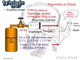
Pneumatics on Robots • Simplified model FORCE= Area of Diaphragm (inches) X Pressure (PSI) in tank. Whoa! That’s a lot of force Pneumatic Cylinder Safety Glasses Compressed Air Tank 60 lbs Geek Plunger Diaphragm For a 1.5” cylinder bore area r2 = (1.5/2)2 = 1.77 in2 Force = 1.77 X 60 lbf/in2 = 106.2 lbs of Force
Pneumatic Parts • Compressor, 125 PSI, 20 Amps Max, Weight 2.4 lbs • Provides source of pneumatic power • Pressure Switch & gages, 115 PSI high pressure circuit • Pressure switch turns compressor on and off • On at approx. 100 PSI, Off at 115 PSI • Air Tanks – Reservoir so robot functions are not diminished due to loss of pressure - Stores pneumatic power – like a battery • Compressor output will not always keep up with usage • How many on last year’s robot?
Pneumatic Parts • Regulator to regulate pressure to components: • Single & Double Solenoid Valves: electrical control from cRio • Flow Control Valves Change speed of extending and retracting: Usually it is 60 PSI or Less; 2 Regulators are provided for regulating High Pressure System 115 PSI and Low pressure system 60 PSI simultaneously. Single=> On=Extend, Off=Retract Double=> Side 1 On Pulse Extend Side 1 Off Same Position Side 2 On Pulse Retract Side 2 Off Same Position Too Fast, Slow it down with Flow control.
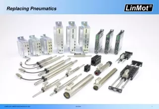
Pneumatic Parts • Valve to Release or Fill with Air • Fittings • Cylinder (Various Sizes) Teflon tape helps prevent leaks at connections – don’t use too much Diameter Range: ½” to 2” Stroke Range: ½” to 24”
Application Information • Force Range @ 100 PSI • Rod diameter – ¼” to ½” • ¼” may bend when robots crash into each other • Mounting options
Rotary Actuator • Rotary Actuator Rotational Force =Torque (0.075/2)2 * PI X 60 PSI = 0.26 ft-lbs (0.875/2)2 * PI X 60 PSI = 36 ft-lbs (1.06/2)2 * PI X 60 PSI= 52 ft-lbs
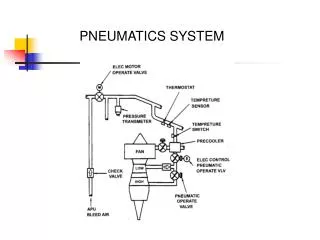
Pneumatic diagram High pressure 115 PSI Low pressure 60 PSI
Pros and Cons of Pneumatics • Reasons for using Pneumatics • Weight: May be less total weight than using Gears and Pulleys & multiple electrical motors while keeping the same Force • Simple to Design/Easy to Build: A closed loop pneumatic system is easier to design than gears and pulleys. • Reliable: Pneumatics perform the same over and over again • Force is adjustable and the Force cylinders produce can be significant. • A variety of pneumatic cylinders are offered • We will probably have cylinders already for shifting 2 speed gearbox • Potential Issues with Pneumatics • Pneumatic support system weight – compressor, tanks, regulator, gages • Need all of these components whether we use 1 or 10 cylinders • Stroke Length is limited to 2 ft max. (There are limits). • Fixed increments of travel – full stroke in or out limited variable positions • Need to make sure system is charged before every match • Leaks are possible and can be annoying to find – always plan on putting compressor on robot to avoid complete robot system shut-down