Download
1 / 37
370 likes | 494 Views
3-D Scanning Robot. Steve Alexander Jeff Bonham John Johansson Adam Mewha Faculty Advisor: Dr. C. Macnab. Overview of Presentation. Project Goal Background of 3D Scanning Structural and Mechanical Design Software Design Control Communication Visualization Results. Project Goal.

E N D
3-D Scanning Robot Steve Alexander Jeff Bonham John Johansson Adam Mewha Faculty Advisor: Dr. C. Macnab
Overview of Presentation • Project Goal • Background of 3D Scanning • Structural and Mechanical Design • Software Design • Control • Communication • Visualization • Results
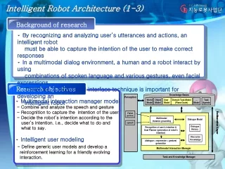
Project Goal • Create an autonomous robot which will scan an object and create a 3-D representation of that object on a computer
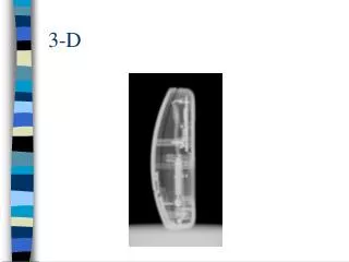
Background of 3-D Scanning Basic Idea • Create a 3-D representation of an object which can be viewed on a computer
Background of 3D Scanning Existing Scanning Methods • Laser • Photogrammetry • Direct Contact • Sound Waves
BackgroundMechanics • Decided to go with a three-joint arm using a direct-contact method • Using Lego for the design • Advantages • Low Cost • C Programming Interface • Wide Variety of Parts Leading to Easier Structural Design And Redesign
BackgroundMechanics • Disadvantages • Limited Number of Input And Output Connections • Limited Processing Power • Gear Backlash And Structural Flexibility • Result: Poor Accuracy
Background Mechanics • Sample gears and gear reduction Diagrams from D. Baum, "Definitive Guide to Lego Mindstorms",2nd ed.
Mechanics of the Current Design • Successfully implemented stated goal of designing a robot arm with 3 Degrees of Freedom on a linear tracking base
Kinematics/Mechanics of the Current Design Side view representation of the finished arm. Equation to convert the above angles and lengths into Cartesian coordinates
Mechanics of the Current Design • January 2003 identified three main areas which required significant changes to be able to have a functional unit • Complete redesign of Wrist/End-Effector • Redesign/manufacture of axel support • Complete redesign of drive system
Wrist / End-Effector • Problems Identified • End wheel too large • Length not easily adjusted • Not enough reduction on rotation sensor
Wrist / End-Effector • 1 and 2 easily fixed • Smallest available gear used as most distal point (finger) • Axel used as attachment of distal point to main arm
Wrist / End-Effector Third design change more difficult. Tried to implement above design (8.3X reduction). Excessive torque at rotation sensor, wrist joint unable to move freely.
Wrist / End-Effector • Settled on this final design giving a reduction of 5
Drive System Original Base December 2003 Original Single wheel drive December 2003
Drive System New centrally mounted guide for base (left) and robot (right) Final design for drive system
Axels • In order to support weight of Chassis employed #10 threaded rod as axels. Attached wheels via threaded inserts and lock nuts.
Control Software Control Software Progression • Version 1.1 • Turned the motors on and off, varied the speed • Version 1.2 • Rotary encoders used as an input to control the stop position of each motor
Control Software Control Software Progression • Version 1.3 • A Proportional controller was implemented. This enabled us to have the motor speed slow as the target position was approached.
Control Software Additions in Version 1.5 to Version 2.3 • Incorporated feedback loop control for the Elbow joint which tracks the position of the shoulder • Single direction communication added between RCX and PC • Multiplexing functionality using external multiplexing board
Control Software Additions in Version 1.5 to Version 2.3 • Added functions for recording data during a scan pass • Extensive calibration was carried out to optimize all portions of a scan
Control Software Calibrate Move Base to Next Scan Region Reset Arm To Scan Start Position Turn on Shoulder Motor Calculate Elbow Position If Scan Finished Transmit Data to PC
Communication Software • Need to transmit scan data from robot to PC for processing • LegOS Networking Protocol (LNP) too complex • Use IR program by Pavel Petrovic • Based on small subset of LNP • Simple unidirectional communication • Basic CRC
Communication Software First Version • Batch file to call IR multiple times • Very unreliable • Manually timed • No flexibility
Communication Software Second Version • IRG (IR Good) Program • Total solution • Fully automated • High complexity • Many issues • Abandoned
Communication Software Third Version • IRR (IR Redone) • C equivalent of first version • Calls IR four times with a delay • Worked perfectly • Only works for one scan
Communication Software Start Loop Listen for Start of Scan Receive Travel Delay Receive Wrist Delay Receive Elbow Delay Receive Shoulder Delay
Communication Software Need a program to listen for the start of a scan • Developed Listen Program • Continuously read serial port • Listen for a 4-byte start-of-scan message • Message is simply “SCAN” • Return to IRR when done
Communication Software Start Open Com Port Loop Check For Data New Data No Delay Yes Read New Data No Search For Message Found Yes Quit
Communication Software Final version (IRR + Listen) • Fully automated scan • Errors in transmission are unrecoverable • Must discard an entire pass
Visualization Software Matlab software • Load in all scan files • Compute the position of the arm based on rotation sensors • Polyfit data to smooth results • Layer scan passes • Use Matlab “mesh” command
Visualization Software Raw and fitted data for shoulder, elbow, and wrist
Results • Scanning works • Accuracy is poor • Largely due to Lego limitations • Polyfitting smoothes result but wrecks sharp edges • Can be improved with better construction • No 4th-dimensional data • Time and resource constraints